Tibbit Sockets and Tiles
As long as you follow electrical specifications for Tibbits, you can use and interconnect them in any way you like. This manual teaches a structured approach based on Tibbit sockets and tiles. This is the approach used by the Tibbo Project System.
We will use the term Tibbit socket (or simply socket) to denote a landing space for a Tibbit. "Socket" here does not mean a physical socket into which a Tibbit can be plugged. Rather, it describes a space on the board that can accommodate a Tibbit device. This is not to say that actual physical sockets aren't there. In fact, Tibbits are installed on physical sockets most of the time. Our Size 2 and Size 3 Tibbo Project PCBs (TPPs) offer a pair of physical sockets for each Tibbit socket.
More strictly, we will use the term Tibbit socket to describe landing spaces for single-width C1 or M1 devices. Of course, the sockets for M1 and C1 modules are different.
The following diagrams depict a section of the TPP3 — a single tile with sockets (S5), (S6), (S7), and (S8).
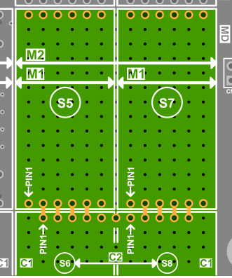
A Tibbit socket for "M" modules occupies 7 x 14 board "squares" (one "square" is 2.54 x 2.54 mm) and has two six-pin physical sockets. M2 devices require two Tibbit sockets next to each other. In the first diagram, (S5) and (S7) are "M" sockets. Note how there is an arrow with the M2 mark — it indicates that an M2 device will occupy both S5 and S7.
A Tibbit socket for "C" modules occupies 7 x 4.5 board "squares." C2 devices take two Tibbit sockets. In the picture above, (S6) and (S8) are "C" sockets. Notice how this socket pair shares a single 11-pin physical socket. This is because C2 devices have 11 pins.
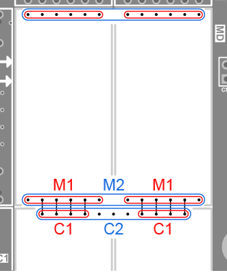
A pair of "M" sockets and a pair of "C" sockets together form a tile, as shown in the first picture. The second diagram illustrates how the pins of M1, M2, C1, and C2 modules plug into the tile's sockets.
A single tile can accommodate Tibbits of different sizes and in various combinations:
- Up to two C1 and up to two M1 devices
- Up to two C1 and one M2 device
- One C2 device and up to two M1 devices
- Up to two H1 modules