Serial Port and General-Purpose I/O Lines
Main conn., #3 |
P3 DTR* |
Input/output Output |
General-purpose input/output line Data terminal ready output |
Main conn., #4 |
P2 DSR* |
Input/output Input |
General-purpose input/output line Data set ready input |
Main conn., #9 |
RX |
|
Serial receive line |
Main conn., #10 |
TX |
|
Serial transmit line |
Main conn., #11 |
P4 CTS/SEL* |
Input/output Input |
General-purpose input/output line Clear to send input; full-/half-duplex selection input |
Main conn., #12 |
P5 RTS/DIR* |
Input/output Output |
General-purpose input/output line Request to send output (full-duplex mode); data direction control output (half-duplex mode) |
* Implemented in (supported through) firmware.
The EM203A features a serial port (RX, TX lines) and several general-purpose I/O lines P2-P5 (there are no lines P0 and P1; line names were selected for naming compatibility with the EM100 ). All of the above lines are of CMOS type. From the hardware point of view, all general-purpose I/O lines can serve as inputs or outputs. Maximum load current for each I/O line is 10mA.
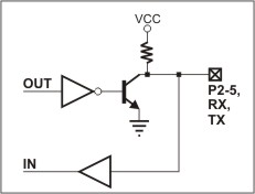
Simplified structure of EM203A's I/O lines is shown on the circuit diagram below. All lines are "quasi-bidirectional" and can be viewed as open collector outputs with weak pull-up resistor. There is no explicit direction control. To "measure" an external signal applied to a pin the OUT line must first be set to HIGH. It is OK to drive the pin LOW externally, while the pin outputs HIGH internally.

The serial-to-Ethernet firmware of the EM203A maps certain serial port functions onto the general-purpose I/O pins- these functions are shown in blue in the table above. For example, P5 is a universal input/output but the application firmware can be set to turn this line into the RTS output of the serial port. Therefore, depending on your application, you can view P5 as a general-purpose I/O line or specific control line of the serial port (RTS).
Being of CMOS type, the serial port and I/O lines of the EM203A can be connected directly to the serial port pins and I/O lines of most microcontrollers, microprocessors, etc. An interface IC, such as the MAX232, must be added to the EM203A externally if you want to connect the module to a "true" serial port (for example, COM port of the PC).
Logical signals on the serial port lines of the EM203A are active LOW. TX and RX lines are high when idle, start bit is LOW, stop bit is HIGH; LOW on CTS and RTS lines means "transmission allowed" and HIGH means "transmission not allowed". This is standard for CMOS-level serial ports and is exactly opposite to the signalling on the RS232 cables. Logical signals on the EM203A are inverted because standard RS232 ICs, such as the MAX232, invert the signals internally one more time.
As explained earlier, actual functionality of the I/O lines is firmware-dependent.