Ethernet Lines and Jack/Magnetics Data
Mag. conn., #1 |
RX+ |
Input |
Ethernet port, positive line of the differential input signal pair |
Mag. conn., #2 |
RX- |
Input |
Ethernet port, negative line of the differential input signal pair |
Mag. conn., #9 |
TX+ |
Output |
Ethernet port, positive line of the differential output signal pair |
Mag. conn., #10 |
TX- |
Output |
Ethernet port, negative line of the differential output signal pair |
Mag. conn., #11 |
AVCC |
Output |
"Clean" 1.8V power output for magnetics circuitry |

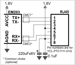
Ethernet port of the EM203 is of 10/100BaseT type. Onboard electronics of the EM203 do not include Ethernet magnetics, so magnetics circuitry must be connected externally to pins TX+, TX-, RX+, RX-, and AVCC. The AVCC pin outputs clean power for the magnetics circuitry, which is very sensitive to noise. The voltage on the AVCC output is 1.8V.
To reduce EMI you can optionally add common chokes into the TX and RX lines. Correctly selected common choke will have little negative impact on "useful" Ethernet signals, yet may substantially reduce unwanted EMI.
|
Do not interconnect the AVCC and VCC pins! This will permanently damage the EM203. |
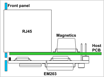
One possible (but not the only) way to place the EM203 on the host PCB is shown on the drawing below. The EM203 is installed on the bottom side of the host board, while a standard RJ45 jack and magnetics are placed on the top side of the board (alternatively, a jack with integrated magnetics can be used). In this configuration, the EM203 takes minimal board space and its LEDs are positioned close to the front panel of the host device. A small opening or window in the host device's housing will allow the LEDs to be visible from the outside.

Another option is to combine the EM203 with the RJ203 jack/magnetics module.