AN012, Creating an Integrated Power Supply
This AN is aimed at OEMs and customers integrating Tibbo modules within their existing products. It covers how to create a reliable power supply which can stably power an EM200 module (for example) with input voltage as low as 9V or as high as 35V.
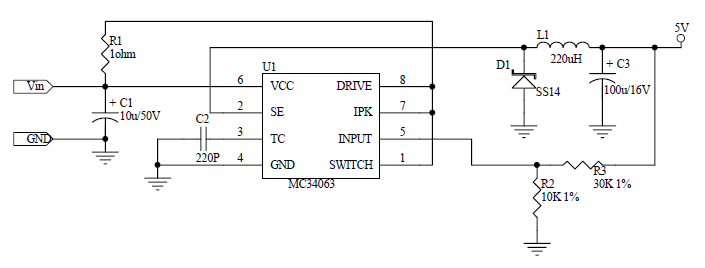
Following is the schematic:

Notes:
| • | U1 (MC35063) is a very popular power IC manufactured by ON Semiconductor. |
| • | R1 is very important. It is just 1 (one!) Ohm, but we really do not recommend the user to omit it. |
| • | R2 and R3 are "1% tolerance" (high-precision) because they define the output voltage of the power supply. |
| • | C1 and C3 capacitors: Do not use SMD capacitors -- use regular through-hole aluminum capacitors. This really helps reduce noise produced by the power supply. |
This is an analog circuit, so layout matters. Apply reasonable "good layout" effort.
Note that it is not necessary to try and obtain the exact capacitors, diodes, etc that Tibbo currently employs. The part numbers are for reference only.
|
Ideally, one should use an oscilloscope to see what sort of "square wave" the PSU generates, both at low and high input voltages. R1 can be adjusted to achieve a better (cleaner) square wave signal on a particular PCB layout. There are no recipes here -- just try and see what works for your circuit. |