Electrical Connections on a Tile
The diagram below shows the electrical connections of a tile. If you are making your own board or using a prototype board, you can connect Tibbits in any way you like (as long as it doesn't cause them to smoke and burn). The diagram illustrates our own structured approach to building things with Tibbits.
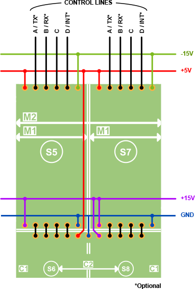
The GND, +5V, +15V, and –15V rails are explained in the Tibbit Power Lines topic.
Eight control lines of the tile — four per "M" socket — go to the CPU of the Tibbo Project PCB (TPP).
"C" sockets and "M" sockets are interconnected directly (see the eight short black lines).
A word on the naming of control lines: "M" sockets (these are (S5) and (S7) in the diagram above) have control lines A, B, C, and D. M1 Tibbits have a matching set of control lines A-D. M2 Tibbits have eight control lines, A-H. When you plug an M2 device into the tile, its control lines correspond to the control lines of the tile as follows:
|
M2 Tibbit |
Corresponding control line on a tile |
|
A |
First "M" socket1, A |
|
B |
First "M" socket1, B |
|
C |
First "M" socket1, C |
|
D |
First "M" socket1, D |
|
E |
Second "M" socket2, A |
|
F |
Second "M" socket2, B |
|
G |
Second "M" socket2, C |
|
H |
Second "M" socket2, D |
- (S5) in the diagram
- (S7) in the diagram