Tibbit Power Lines
The main supply voltage for Tibbits is +5V, and some also need +15V and –15V power. C1 modules have no standard ground and +5V pins, while C2 devices do not have a provision for –15V power. Finally, some Tibbits do not require any power. Here, we provide a more detailed explanation of Tibbit power lines.
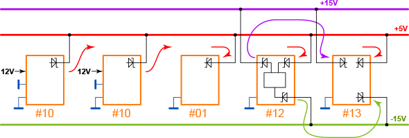
The diagram above shows five Tibbits. Two of them are #10 (+5V power supply), one is a #01 (four-line RS232 port), another one is a #12 (+15V and –15V power supply), and the last one is a #13 (ADC converter).
Notice how all five Tibbits have diodes in their power lines. On power-consuming Tibbits (#01 and #13), these diodes prevent damage to the module if power is accidentally applied in reverse. On power-generating Tibbits (#10 and #12), the diodes allow you to bank power sources. By having two power supply Tibbits, you can either combine their current output or increase reliability by having several redundant power sources.
Power, of course, can also be applied to the power rails externally (i.e., from a lab power supply). Tibbo's Size 2 and Size 3 Tibbo Project PCBs have power terminals for direct 5V power input. However, the boards do not have direct inputs for +15V and –15V. So, although they have +15V and –15V power rails, the only way to have power on them is to insert a Tibbit #12. You only have to do it if there are Tibbits in your system that require these optional voltages. On the above diagram, Tibbit #13 requires +15V and –15V.
One additional point. Power supply Tibbits that provide +5V power generate it from external power sources. For example, Tibbit #10 takes DC input in the 9-18V range, while Tibbit #23 implements PoE (power-over-Ethernet). Both take external power and convert it into +5V. Tibbit #12, however, generates +15 and –15V from the 5V power rail.