Demo #2 — WebPWM
In the previous chapter, we connected a WM2000 to a wireless network and securely transmitted data polled from the WM2000EV's integrated light and temperature sensors to the cloud.
In this chapter, we will:
- Configure the WM2000 for wireless connectivity and debugging using L.U.I.S. (Loadable User Interface System) and the Companion App.
- Load an application into the WM2000 via TIDE.
- Use a web interface to directly manipulate the module's pulse-width modulation (PWM)-capable lines.
Configuring the WM2000 for Wireless Connectivity and Debugging
The WM2000 is Tibbo's first programmable module capable of storing two compiled Tibbo BASIC/C application binaries referred to as "APP0" and "APP1" (only one can run at any given time). Every WM2000 ships preloaded with the Companion App as APP0. This app provides direct access to the Device Configuration Block (DCB) parameters through the L.U.I.S. app, which is available as a web app or a smartphone app for iOS and Android.
While the previous chapter's demonstration app featured built-in settings for directly configuring wireless connectivity, in this example we'll use the Companion App to connect the module to your wireless network. Note that because such settings are saved in the DCB, if you completed the first tutorial you won't need to reconfigure your Wi-Fi, but you will still need to use the Companion App to enable wireless debugging.
The WM2000 can be forced to boot into APP0 — that is, the Companion App if this is what resides in your module's APP0 space — through the use of the MD button. The M/L V4 Flowchart shows how to do this. Alternatively, follow this infographic detailing the shortest path to launching APP0:

Once the Companion App is running, you can interact with it through the L.U.I.S app. Launch your preferred version of the L.U.I.S. app and select WM2000 Companion to connect to your WM2000.
After connecting , you will be able to modify the DCB settings. Here is what you need to touch:
- Set Autoconnect to Yes
- Enter your Wi-Fi SSID and Wi-Fi Password (if you didn't do this in the previous chapter)
- Set Debug Mode to Wi-Fi
- Set DHCP to Yes
When you're done, click Save and then Reboot.
Uploading and Using the WebPWM App
Now that you've configured the wireless interface on your WM2000, you can use TIDE to upload and debug applications, just like on Tibbo's "wired-first" programmable devices. In this chapter, we'll be uploading the WebPWM demo app from the WM2000EV Project Repository.
1. Clone the repository to your computer.
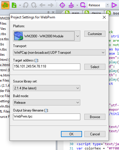
2. Open WebPwm.tpr in TIDE.
3. Make sure that the Transport option is WinPCap (non-broadcast) UDP Transport.
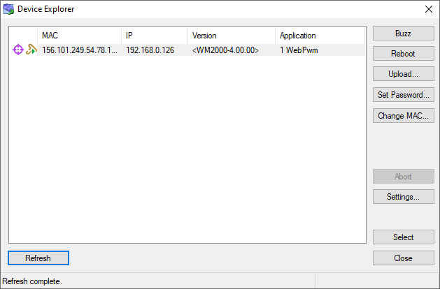
4. Click Select next to the Target address field; this will launch the Device Explorer.
If your computer is on the same network as the WM2000, you'll see your module in the list. Write down the IP address; you'll need it to access the web interface.
Note the "1" before the name of the application — this indicates that the device is running APP1.
In the Device Explorer:
5. Double-click on the WM2000 to select it as a debug target. This will return you into the Project Settings window. Click OK.
6. Before running the project, make sure that the compilation mode is set to Release.
7. Click Run (or press F5). The demo application will be uploaded into the WM2000, then the module will reboot and start executing the application.
In your browser:
8. Open a new browser window and type your WM2000's IP address (you recorded it earlier, remember?) into the address bar.
9. When the page loads, use the color picker to select the color of the WM2000EV's integrated RGB LED. You can also use the red, green, and blue sliders to adjust each color channel's level separately.
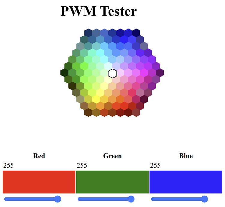
Note #1: The RGB LED is not calibrated for color accuracy, so there might be some discrepancy between what you see on the screen in the color picker and the output of the device. Placing a sheet of regular white paper over the LED will diffuse its output, which will improve color rendition.
Note #2: In this demo, the WM2000's PWM channels are only driving a single RGB LED, but you can use the same control method to drive a large number of LEDs; for example, an RGB LED strip. The PWM control method will remain the same. However, because the current consumed by an LED strip is much higher than the current of a single LED, controlling the strip will require a few power FETs between the WM2000's PWM outputs and the strip.
Debugging the App
With the Autoconnect option set to Yes, and the Debug Mode set to Wi-Fi, you can now debug Tibbo BASIC/C applications over Wi-Fi. The process is identical to that for traditional wired Tibbo devices: Simply change the compilation mode to Debug and run your application.
Note that if your application sends a significant number of debug messages (the sys.debugprint method), you may experience some performance degradation. This is because debug communications use UDP, and many Wi-Fi access points limit the number of UDP packets they allow to pass through each second.