WM2000EV
The WM2000EV is an evaluation kit designed for evaluating the capabilities of the WM2000 Programmable Wireless IIoT Module. One module is included in the kit and is preloaded with a demonstration app — the first chapter of our guided journey of exploration for the WM2000. Also included in the kit are a USB Type-C-to-A cable, a CR2032 button cell battery, and four jumpers installed in their default positions.
The WM2000EV was designed to be completely self-contained and enable the exploration of the module's features without the need to wire in any external circuitry. It is equipped with all essential buttons and status LEDs, integrated light and temperature sensors, an RGB LED controlled by three I/O lines with pulse-width modulation (PWM) output, a backup battery, and the circuitry necessary for enabling the WM2000's low-power "sleep" mode.
The module is connected and secured to the WM2000EV through a unique lock-and-release mechanism consisting of two rows of horizontal spring-loaded pins. This mechanism allows for the effortless removal and insertion of the module and ensures reliable connections to its pins. Two 12x2 male pin headers are integrated into the board to facilitate the connection of external components.
The kit is powered either through a two-pin terminal block for 3V-5.5V input or via the USB Type-C connector, which also allows for the serial debugging of the WM2000.
The jumpers toggle the power source for the module's real-time clock and enable or disable the low-power mode, as well as allow for measuring current consumption of the board and/or module.
In addition to hosting all the primary hardware, the WM2000EV's front plate features quick-response (QR) codes linking to the L.U.I.S. (Loadable User Interface System) web app. The backplate has "unboxing" instructions and a QR code linking to the Getting Started guide.
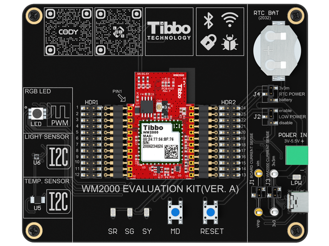
Diagrams


Hardware Features
- Two horizontal rows of spring-loaded pins hold the WM2000 in place
- The module can be easily popped out and popped back in
- I²C temperature sensor
- I²C light sensor
- A large RGB LED driven by three pulse-width modulation (PMW)-capable lines
- Two buttons:
- MD — Connected to the MD line
- Reset — Connected to the RST (reset) line
- Four status LEDs:
- Green (SG), red (SR), and yellow (SY) main status LEDs
- A blue LED (LPW) indicating if the power is applied to the board
- Jumpers and test points:
- For measuring the current of the WM2000 and the entire board
- For enabling the low-power mode
- For selecting the RTC power source (3.3V or backup battery)
- Two 12x2 male pin headers for connecting to external circuitry
- Kit dimensions (L x W x H): 100 x 120 x 27.5mm
- Tibbo BASIC/C applications can be debugged via Wi-Fi or USB
- A USB Type-C connector for powering the board and serial debugging
- A two-pin terminal block for connecting external 3V–5.5V power*
- A CR2032 backup battery (in a holder)
- External circuitry required to enable the WM2000's low-power mode
- A USB Type-C-to-A cable is included with the kit
* Only needed if power is not applied via the USB port