#13, M1S: Four-Channel ADC

Function: Four-channel ADC
Form factor: M1S
Category: Input module
Special needs: +15V and -15V power (use Tibbit #12 to generate these voltages)
Power requirements: 5V/10mA, 15V/9mA, –15V/3.5mA (the aggregated consumption through Tibbit #12 is 66mA)
Mates with: #19, #20, #21 (limited use)
See also: #61-1, #61-2, #12, #14, #31, #43-1, #52, #53


Details
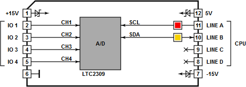
This analog-to-digital converter (ADC) Tibbit is based on the LTC2309 12-bit ADC with an I²C interface. Tibbit #13 uses only four channels of this ADC. The analog front end of the module allows you to measure signals in the –10V to +10V range. All measurements are relative to the system ground.
Keep in mind that every time you read data out of the LTC2309 IC, you are actually getting the previous conversion result. This may not be an issue when running a conversion loop for a single ADC channel.
You will have to ignore the first result in these cases:
- After a channel change: Only the second measurement will bring you the conversion data for the newly selected channel.
- Sporadic measurements: Do the conversion twice and discard the first result. This way, you will obtain the "current" data.
The LTC2309 ADC IC has a 12-bit resolution. Tibbit #13 has an effective resolution of about 9~10 bits. This reduction is caused by system noise and other factors that affect measurement quality.
Combine Tibbit #13 with #20 (nine terminal blocks) or #19 (DB9M connector). It's possible, but not common, to use the latter for wiring into the ADC inputs.
Tibbit #21 (four terminal blocks) can also be used, but you will have to steal the ground from elsewhere, as it doesn't have its own ground line and the ADC measures input voltages relative to the system ground.
LEDs
There is one red and one yellow LED. The red LED is connected to the SCL line of the I²C interface and the yellow LED to the SDA line.
Sample Project
The use of Tibbit #13 is illustrated by a Tibbo BASIC test project. You can find it here: https://github.com/tibbotech/CA-Test-Tibbits-13-14.
