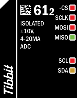
#61-2, H2T: ISOLATED ±10V, 4-20mA ADC

Function: Isolated two-channel ±10V and two-channel 4-20mA ADC
Form factor: H2T
Category: Input module
Special needs: ---
Power requirements: 5V/35mA
Temperature range: –40°C to +85°C
Mates with: ---
See also: #61-1
Details
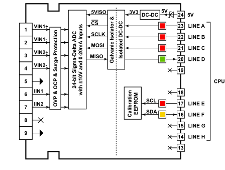
This Tibbit is an isolated 24-bit ±10V and 4–20mA Sigma-Delta (Σ-Δ) analog-to-digital converter (ADC). It offers two differential ±10V channels or four 0–10V single-ended channels, as well as two single-ended current-sinking channels. All lines feature overvoltage protection (OVP), overcurrent protection (OCP), and electrostatic discharge (ESD) transients. The integrated ADC chip provides sampling rates ranging from 1.25SPS to 31.25kSPS.
The library that drives this Tibbit handles all calculations and conversion corrections without requiring any MCU integration into the Tibbit. An onboard EEPROM is included to store calibration coefficients, which are determined at the factory and cannot be modified by the user. This EEPROM is write-protected. The Tibbit interfaces with the host CPU of the Tibbo Project PCB (TPP) via a galvanically isolated SPI port and reads calibration parameters via an I2C interface to compensate for non-linearity or offset of the ADC chip.
Tibbit #61-2 operates using only a main 5V power source. To accept inputs greater than 5V, the internal ADC chip operates on a single supply, while internal DC-DC converters generate the voltage rails required for operation. Therefore, there is no need for an external dual-rail power (Tibbit #12).
This Tibbit is an H2T hybrid Tibbit that incorporates a 9-pin terminal block into the design. As a result, it does not mate with any other Tibbit. The Tibbit’s analog front-end is completely isolated from the digital interface, and the isolated ground is exposed on pin #5 of the terminal block. We recommend against connecting this line to the TPS ground to maintain isolation and ensure the Tibbit’s precision.
For information on the operating parameters of Tibbit #61-2, please see Specifications.
Control Lines
This Tibbit has six control lines:
|
-CS |
The chip select pin of the Tibbit for SPI interface. The line is HIGH when idle. |
|
SCLK |
The clock input of the Tibbit. The host CPU uses this line to feed the clock for data transmissions. The line is LOW when idle. |
|
MOSI |
This is the data in (DIN) of the Tibbit for SPI interface. Used by the host CPU to transfer data from the host CPU to the Tibbit. The line is LOW when idle. |
|
MISO |
This is the data out (DOUT) of the Tibbit for SPI interface. Used by the Tibbit to transfer data from the Tibbit to the host CPU. The line is LOW when idle. |
|
SCL |
The clock input line of the EEPROM. The line is HIGH when idle. |
|
SDA |
The data line of the EEPROM. The line is HIGH when idle. |
Analog Front-end (Terminal Block Connector)
Tibbit #61-2 is a hybrid device integrating a terminal block connector.
Connector pin assignment is as follows:
|
# |
Pin Name |
Description |
|
#1 |
VIN1+ (input) |
Differential Voltage Input channel 1 (+) |
|
Single-ended Voltage Input channel 1 (+) |
||
|
#2 |
VIN1- (input) |
Differential Voltage Input channel 1 (-) |
|
Single-ended Voltage Input channel 2 (+) |
||
|
#3 |
VIN2+ (input) |
Differential Voltage Input channel 2 (+) |
|
Single-ended Voltage Input channel 3 (+) |
||
|
#4 |
VIN2- (input) |
Differential Voltage Input channel 2 (-) |
|
Single-ended Voltage Input channel 4 (+) |
||
|
#5 |
Isolated ground |
Isolated ground (same as #9)* |
|
#6 |
IIN1 (input) |
4-20mA Current Input 1 |
|
#7 |
IIN2 (input) |
4-20mA Current Input 2 |
|
#8 |
NC |
Not Connected |
|
#9 |
Isolated ground |
Isolated ground (same as #5)* |
* We recommend against connecting this line to the TPS ground to maintain isolation and Tibbit’s precision.
LEDs
Control lines A~F are each equipped with an LED. All the lines have red LEDs except MISO and SDA lines. The MISO line is equipped with a green LED, while the SDA line has a yellow LED. An LED will turn on when the state of its corresponding line is LOW.
Library Support and Sample Project
Tibbit #61-2 is supported by a Tibbo BASIC library, which takes care of calculations and conversions for you. In addition, Tibbit #61-2 is fully supported in AppBlocks, our no-code, flowchart-based, in-browser hardware configurator and development platform.
You can also refer to Tibbit #61's sample project for integration support.
Differential Mode and Single-Ended Voltage Inputs
Tibbit #61-2 offers two differential ±10V voltage inputs, which are recommended over single-ended inputs due to their high noise rejection capability and wider input range. For differential inputs, you do not need to connect the isolated ground between the sensor and the Tibbit. To reduce noise, you can connect the signal cable's shield to the isolated ground (terminal block pins #5 or #9). When connecting the isolated ground, care must be taken to ensure that the common-mode voltage of the positive and negative inputs does not exceed ±20V. Protection is in place to prevent damage, but prolonged exposure to excessive common-mode voltage may cause degradation.
Tibbit #61-2 also offers four single-ended channels capable of reading 0–10V analog inputs with reference to the isolated ground (terminal block pins #5 and #9). If additional channels are needed, the Tibbit's voltage inputs can be used as single-ended by connecting the signals appropriately and configuring the Tibbit mode via software library functions. However, increasing the number of channels comes at the cost of reduced input voltage range, signal-to-noise ratio (SNR), and precision. In single-ended mode, the isolated ground pin (terminal block pins #5 and #9) must be connected.
The voltage and current inputs feature overvoltage protection (OVP), voltage transients, and electrostatic discharge (ESD). The voltage input diagram for Tibbit #61-2 is below:
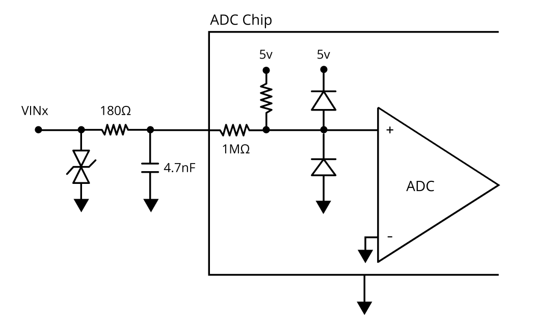
 Do not connect the isolated ground (terminal block pins #5 and #9) to the ground of Tibbo Project PCB (TPP).
Current Inputs
Tibbit #61-2 offers two single-end 4-20mA current inputs that are current-sinking. This means that the current flows into these inputs rather than current going out of them. The diagram of the pin is as follows:
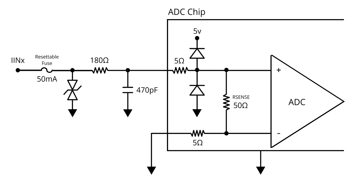
 The current inputs are equipped with circuits to protect against short circuits and overcurrents.