Serial Port and General-Purpose I/O Lines
The EM510 has ten I/O lines: eight general-purpose I/O (GPIO) lines GPIO0~GPIO7, plus TX and RX lines of the serial port.
The I/O lines of the EM510 are NOT 5V-tolerant. The maximum load current for each line is 10mA.
GPIO0 and GPIO1 double as interrupt inputs INT0 and INT1. GPIO1, GPIO3, and GPIO4 can optionally be used to connect an external flash IC. This IC is required if you want to use the fd. object. GPIO5, GPIO6, and GPIO7 can optionally be used to connect to the WA2000 Wi-Fi/BLE add-on module. The add-on is required if you want to use the wln. and bt. objects.
The serial port has four I/O lines: RX, TX, CTS, and RTS. The TX and RX lines belong exclusively to the serial port and are separate from the GPIO lines. The CTS and RTS lines do not exist independently. Rather, either GPIO0/INT0 or GPIO1/INT1 can be selected to serve as the CTS line, while any of GPIO0~GPIO7 can be selected to serve as the RTS line. This is done through the ser.rtsmap and ser.ctsmap properties of the ser. object.
The serial port of the EM510 can work in one of the three modes: UART, Wiegand, or clock/data (TX, RX, CTS, and CTS lines have different names and functions in the Wiegand and clock/data modes).
A simplified structure of one I/O line of the EM510 is shown in the circuit diagram below. Each line has an independent output buffer control. When the EM510 powers up, all its I/O lines have their output buffers tri-stated (in other words, all I/O lines are configured as inputs). With the exception of several cases listed below, you need to programmatically enable the output buffer of a GPIO line if you want this line to become an output.
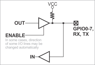
Cases When I/O lines Are Controlled Automatically
Direction configuration of TX and RX lines happens automatically when the serial port is in the UART mode: Setting ser.mode = 0 — PL_SER_MODE_UART and ser.enabled = 1 — YES for the first time automatically configures the TX line as an output, while the RX line remains an input. The same is not true for Wiegand and clock/data modes. Once the serial port is enabled, you lose the ability to control the TX line (set it HIGH or LOW) programmatically. Disabling the serial port (ser.enabled = 0 — NO) does not alter the direction configuration of the TX line.
Another group of pins that will be configured and controlled automatically are the pins responsible for communicating with the external flash IC. When the fd. object is enabled, GPIO1, GPIO3, and GPIO4 are automatically handled by TiOS and your application should not attempt to manipulate these lines at the same time. The fd. object is enabled in the Project Settings dialog of Tibbo IDE (TIDE). To enable, click on the Customize button (in the Project Settings dialog) and set Flash disk (fd.) object to Enabled.
Note that the interface lines of the WA2000 must be enabled in your code, as this will not happen automatically. For more information, see Connecting WA2000 to Tibbo Devices.
For more information, please refer to the documentation for the fd., bt., ser., io., and other objects. Additionally, refer to the EM510 platform documentation.