Tiles, Sockets, Connectors, Controls
The TPP2 features six "M" and six+one "C" sockets.
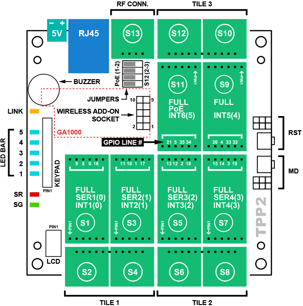
Sockets (S1) ~ (S12) form three standard tiles.
There are 24 control lines connecting "M" sockets to the CPU — four per each socket.
Additionally:
- "M" sockets (S1), (S3), (S5), and (S7) have the UART capability.
- "M" sockets (S1), (S3), (S5), (S7), (S9), and (S10) have the interrupt capability.
- "M" socket (S11) has the PoE capability, provided that four TPP2 jumpers are set to 1-2 position (see below).
- "C" socket (S13) exists exclusively for the installation of the RF connector Tibbit #37. This socket has no other functions.
Jumpers
Four jumpers next to the RJ45 jack define the connection between the "M" socket (S11), "C" socket (S12), and the RJ45 jack:
- When the jumpers are in the 1-2 position, four power lines from the RJ45 jack are connected to four I/O lines of (S11). Under this arrangement you can install an M1 PoE device into the (S11), or M2 PoE device into the (S9)-(S11).
- When the jumpers are in the 2-3 position, the RJ45 jack is disconnected from the socket (S11). The socket (S11) is instead connected to (S12) in a "standard tile way."