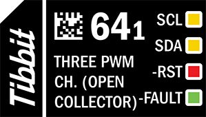
#64-1, M1T: Three PWMs With Open Collector Outputs

Function: Three PWM channels with open collector outputs
Form factor: M1T
Category: Output module
Special needs: [INT] (Optional)
Power requirements: 5V/35mA (minimum — see the note in the Details section below)


Details
Tibbit #64-1 implements three pulse-width modulation (PWM) channels through its integrated PIC16F1575 microcontroller. The output frequency and pulse width (duty cycle) are set independently for each PWM channel through I²C registers. Each channel can output a PWM signal within a frequency range of 1Hz to 20kHz with a duty cycle from 0% to 100%. The ability to precisely configure the frequency and duty cycle of each channel makes Tibbit #64-1 suitable for a wide range of applications, including controlling LEDs and motor drives.
The I²C interface is utilized for communications with the main CPU of the host Tibbo Project PCB (TPP) and for PIC firmware updates. Tibbit #64-1 features a simple, user-friendly, and robust Interface Protocol that allows you to directly write your desired frequency and duty cycle for each channel as integers — no calculations are required.
The interface protocol also features error-handling capabilities linked to the –FAULT line. For example, writing an out-of-range value to a frequency register will result in the Tibbit disabling the corresponding channel's output and entering error mode.
Each PWM channel is equipped with open collector transistors. Each channel is rated for 250mA of continuous current at room temperature.
Tibbit #64-1 was designed to be paired with Tibbit #20 (nine terminal blocks) or Tibbit #21 (four terminal blocks), with the ground available via the IO4 line — Tibbit #64-1 outputs voltages with respect to the system ground. While uncommon, it's also possible to use Tibbit #19 (DB9M connector) to wire into the PWM outputs.

As Tibbit #64-1 is not isolated, all output transistors' grounds are shared with the host TPS. If the ground line of a PWM load is not joined with the TPS ground at the connector, then the load current might flow into and disrupt the system's power supply. Therefore, for applications in which connected devices draw a significant amount of power (e.g., LEDs), Tibbo recommends that you use an external power supply for those peripherals and connect the ground to the TPS via the IO4 line at the nearest point to the Tibbit's mating connector.
The PIC microcontroller's firmware can be upgraded in the system and without any additional external hardware. The firmware update process utilizes the low-voltage programming (LVP) mode of the PIC microcontroller, with the SCL line acting as ICSPCLK, the SDA line acting as ICSPDAT, and the –RST line used to put the microcontroller into the LVP mode. Tibbo provides open-source libraries for LVP mode and controlling Tibbit #64-1.
Control Lines
- SCL — I²C clock line. Clock-stretching is supported.

To fully benefit from the clock-stretching capabilities of Tibbit #64-1, Tibbo recommends that you use the i2c. Object if your platform supports it.
- SDA — I²C data line.
- –RST — Reset line, connected to the PIC microcontroller's reset pin.
- –FAULT — This line is an output. Whenever a fault scenario occurs, this line is asserted LOW by the Tibbit, which can initiate an interrupt routine on the host TPP if installed in a socket with an interrupt line. Writing correct values to the configuration registers or resetting the PIC microcontroller will return the line to the HIGH (no fault) state.
 The –FAULT line will remain LOW (in a fault state) until all fault events have been corrected. For example, writing out-of-range values for the frequency registers of two channels will result in two faults. If you only write a value to correct one register, the –FAULT line will still remain LOW.
LEDs
There are two yellow, one red, and one green LED. Both yellow LEDs are connected to the I²C interface — the first to the SCL line, the second to the SDA line. The red LED is connected to the –RST line of the PIC microcontroller. The green LED is on the –FAULT line.
Parametric Specifications
|
Channels |
3 |
|
Frequency range |
1Hz ~ 20kHz* |
|
Frequency resolution (steps) |
|
|
Duty cycle range |
0% ~ 100%* |
|
Duty cycle resolution |
1% |
|
Output type |
Sinking |
|
Maximum sinking capability |
250mA per channel |
* Writing a value outside of this range to the control register will result in a fault.
