#16, M1S: Three PWMs With OC Outputs

FOR NEW APPLICATIONS, TIBBO RECOMMENDS TIBBIT #64-1
Function: Three PWMs with open collector outputs
Form factor: M1S
Category: Output module
Special needs: ---
Power requirements: 5V/20mA
Mates with: #19, #20, #21 (limited use)
Details
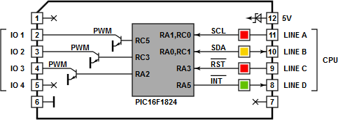
This Tibbit is based on the PIC16F1824 microcontroller and takes advantage of the pulse-width modulation (PWM) channels available on this PIC device. The PIC microcontroller has four PWM channels, but one cannot be used because it shares I/O lines with the I²C interface. The I²C interface is utilized for communications with the main CPU of the host Tibbo Project PCB (TPP) and also for PIC firmware upgrades.
The frequency and pulse width (duty cycle) are set independently for each PWM channel. The frequency is controlled through a divider and a period value. The divider allows you to select the base frequency applied to the divider. Available choices are 32MHz, 8MHz, 2MHz, and 500KHz.
The output signal of the PWM can then be programmed to have a period equal to 4~1,024 base frequency periods in 4-period steps (i.e., 4, 8, 12 ...1,020, 1,024). This gives you an output range from 8MHz down to 488Hz.
The PWM pulse width can be programmed to have a period equal to 1~1,024 base frequency periods in 1-period steps (1, 2, 3 ... 1,023, 1,024).
Each PWM channel uses one Zetex FFMT491 NPN transistor, which is rated for 1A continuous collector current.
Combine Tibbit #16 with #20 (nine terminal blocks) or #19 (DB9M connector). It's possible, but not common, to use the latter for wiring into the PWM outputs. Tibbit #21 (four terminal blocks) can also be used, but you will have to steal the ground from elsewhere, as #21 doesn't have its own ground line and Tibbit #16 outputs voltages with respect to the system ground.
LEDs
There are two red, one yellow, and one green LED. The first red LED is connected to the SCL line of the I²C interface, while the second one is connected to the –RST line of the PIC microcontroller. The yellow LED is connected to the SDA line of the I²C interface. The green LED is on the –INT line.
PIC Microcontroller and GRA Firmware
Tibbit #16 ships with general register access (GRA) firmware, which allows you to access internal PIC registers and memory through the I²C interface. The firmware implements a very simple communications protocol that essentially consists of two important commands — address read and address write. These two commands are used to write to and read from the PIC's internal RAM and registers. This facilitates simple and versatile access to all microcontroller resources. A Tibbo BASIC library sits on top of the GRA firmware and uses the communications protocol to access and set the PWM channels.
As the GRA firmware does not do anything intelligent and all the setup work is essentially scripted in Tibbo BASIC, it is possible to modify a PWM setup (and PIC behavior) without making any changes to the PIC firmware.
The GRA firmware can be updated or replaced using the pic_firmware_upgrade Tibbo BASIC project (see below). You can, therefore, create and run PIC applications that go far beyond providing simple register and memory access.
Sample Project
The use of Tibbit #16 is illustrated by a Tibbo BASIC test project. You can find it here: https://github.com/tibbotech/CA-Test-Tibbits-16-17-31.