Detailed Device Info
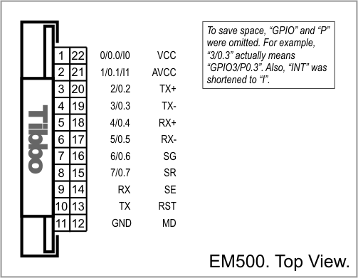
I/O Pin Assignment
|
Pin # |
Function |
Description |
|
1(1,2,3) |
GPIO0/P0.0/INT0 |
General-purpose I/O line 0 (P0.0); interrupt line 0. |
|
2(1,2,3) |
GPIO1/P0.1/INT1 |
General-purpose I/O line 1 (P0.1); interrupt line 1; for flash disk operation, connect to SI and SO of external flash. |
|
3(1,2) |
GPIO2/P0.2 |
General-purpose I/O line 2 (P0.2). |
|
4(1,2) |
GPIO3/P0.3 |
General-purpose I/O line 3 (P0.3); for flash disk operation, connect to CLK of external flash, also connect to 5.1K pull-up resistor to VCC (3.3V). |
|
5(1,2) |
GPIO4/P0.4 |
General-purpose I/O line 4 (P0.4); for flash disk operation, connect to CS of external flash. |
|
6(1,2) |
GPIO5/P0.5 |
General-purpose I/O line 5 (P0.5); for Wi-Fi operation, connect to DI and DO of GA1000. |
|
7(1,2) |
GPIO6/P0.6 |
General-purpose I/O line 6 (P0.6); for Wi-Fi operation, connect to CLK of GA1000, also to reset-generating logic (NAND gates). |
|
8(1,2) |
GPIO7/P0.7 |
General-purpose I/O line 7 (P0.7); for Wi-Fi operation, connect to CS of GA1000, also to reset-generating logic (NAND gates). |
|
9(1) |
RX |
RX, W1, and din input of the serial port. |
|
10(1) |
TX |
TX, W1, and dout output of the serial port. |
|
11 |
GND |
System ground. |
|
12 |
MD |
Mode selection pin. |
|
13 |
RST |
Reset input, active low. Proper external reset is a must. |
|
14 |
SE |
Link status LED control line. |
|
15 |
SR |
Dual-function red status LED control line. |
|
16 |
SG |
Dual-function green status LED control line. |
|
17 |
RX– |
Ethernet port, negative line of the differential input signal pair. |
|
18 |
RX+ |
Ethernet port, positive line of the differential input signal pair. |
|
19 |
TX– |
Ethernet port, negative line of the differential output signal pair. |
|
20 |
TX+ |
Ethernet port, positive line of the differential output signal pair. |
|
21 |
AVCC |
"Clean" power output for magnetics circuitry. |
|
22 |
VCC |
Positive power input, 3.3V nominal, ±5%, max. current consumption 260mA. |
- This line is 5V-tolerant and can be interfaced to 5V CMOS devices directly.
- This line can serve as the RTS/Wout/cout line of a serial port (provided that this does not interfere with any other function).
- This line can serve as the CTS/W0&1in/cin line of a serial port (provided that this does not interfere with any other function).
Additional Resources
See these topics for more information on various hardware facilities of the EM500:
- Serial Port and General-Purpose I/O Lines
- Ethernet Port Lines
- Flash Memory and EEPROM
- LED Lines
- Power, Reset, and Mode Selection Lines