Power, Reset, and Mode Selection Lines
The EM500 should be powered from a stabilized DC power supply with a nominal output voltage of 3.3V (±5% tolerance). The module's current consumption is approximately 260mA. Providing an adequate power supply is very important — a poorly built circuit may affect the EM500's operation. We recommend that you use a switching power supply. One example of such a circuit is shown below.
For revision -00 devices, a proper external reset is a must! The reset pulse should be active LOW. We strongly advise against using low-cost RC circuits and other unreliable methods of generating reset pulses. Reset should be applied for as long as the power supply voltage is below 2.9V. We recommend using a dedicated reset IC, such as the MCP130-300 device from Microchip. This part has a trip point at ~2.95V — perfect for the EM500.
Revision -01 modules have the reset IC onboard and do not rely on the external reset. A master reset input is still provided.
If the EM500 is to serve as a communications co-processor in a larger system that has its own CPU (microcontroller), it is also OK to control the RST line through a general-purpose I/O (GPIO) pin of this CPU. Reset pulses for the EM500 can then be generated programmatically by setting the I/O pin of the CPU to LOW and then to HIGH.
The function of the MD line is described in Setup (MD) Button (Line).
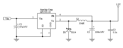
Power Supply Circuit
Many power supply circuits will work well. The one below is used by Tibbo. This circuit can handle input voltages in the 9V~24V range.
Notes:
- U1 (AP1501-33) is a popular power IC manufactured by Anachip (now Diodes Incorporated, www.diodes.com)
- C1 and C2 capacitors: Do not use SMD capacitors — use regular through-hole aluminum capacitors. This really helps reduce the noise produced by the power supply.
- This is an analog circuit, so layout matters. Apply reasonable "good layout" effort.
 Ideally, you should use an oscilloscope to see what sort of "square wave" the power supply generates, both at low and high input voltages, as well as light and heavy loads. There are no recipes here — just try and see what works for your circuit.