LED Lines
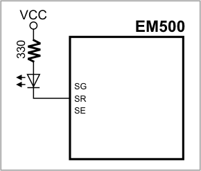
The EM500 has three LED control lines — Status Green (SG), Status Red (SR), and Status Ethernet (SE). All lines have the same internal structure and the LEDs should be connected as shown in the schematic diagram below. The maximum load for each line is 10mA. For a small LED, a 330Ω series resistor will provide sufficient brightness.
The SG and SR lines are used to control two status LEDs found on Tibbo products. These LEDs can show various flashing patterns indicating the current device state (see Status LEDs). On the EM500, there is an added twist: the same pair of status LEDs also indicates the current Ethernet link status through LED brightness. We refer to the EM500's status LEDs as "dual-function LEDs." This is a patented featured available exclusively on our MiniMo® devices. Here is how this works:
When a "live" Ethernet cable is not plugged into the RJ45 jack, flashing patterns displayed by the status LEDs are "dimmed." That is, LEDs turn on at about 20% of their nominal brightness. When a "live" Ethernet cable is plugged into the RJ45 jack, flashing patterns are displayed at full brightness.
This dual functionality was designed into the EM500 for an important reason: Many popular RJ45 jacks have two internal LEDs. With the EM500, it is possible to use these LEDs both for the module state indication, and for Ethernet link indication. This eliminates the need for any additional LEDs.
The third LED control line — SE — is a separate line for Ethernet link indication. The SE LED will be on when the Ethernet interface is in the linked state.
There is no indication of the Ethernet link speed on the EM500. That is, there is no LED control line to indicate whether the link is established in the 10BaseT or 100BaseT mode. Many networked devices have such an LED, but its existence has become meaningless: it is actually very difficult to find any old-style 10Mb Ethernet equipment in active use these days.