EM120/EM200EV
 This is a legacy device. The following information is provided as it was documented originally, albeit with some corrections and changes for clarity and style.

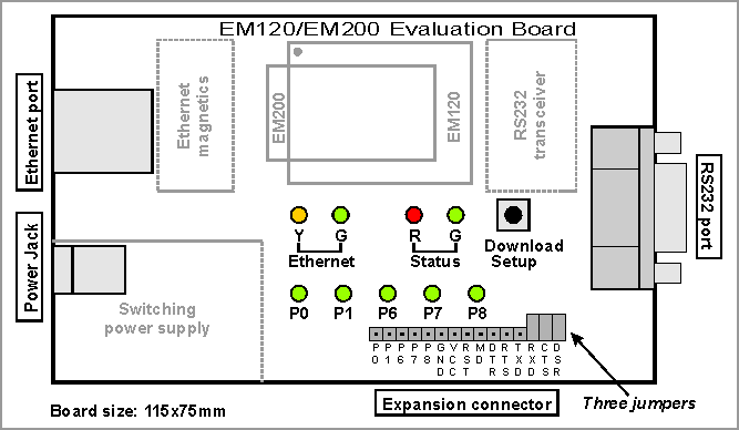
The EM120/EM200EV evaluation board offers a convenient way of testing the EM120 (which is no longer supported as a programmable device) and EM200 embedded modules. The board features the following components:
- A socket for EM120 or EM200 installation
- A power jack and a switching power regulator (12VDC-to-5VDC, adapter current rating must be no less than 500mA)
- An RJ45 connector and 10/100BaseT Ethernet magnetics (EM120 and EM200 do not have built-in magnetics)
- A DB9M RS232 connector and RS232 transceiver (supported signals are RX, TX, RTS, CTS, DTR, DSR)
- Setup button (connected to the MD line of the attached EM120/EM200)
- Two Ethernet LEDs and two status LEDs (connected to LED lines of EM120/200)
- Five additional LEDs connected to lines P0, P1, and P6~8 of the attached EM120/EM200
- A 15-pin expansion connector provides access to the attached EM120/EM200's serial and general-purpose I/O pins (therefore, all I/O lines on this connector are of the TTL type)
