Expansion Connector Pin Assignment
The 15-pin expansion connector of the EM120/EM200EV has the following pin assignments:
|
P0 |
Connected to pin P0 of EM120/EM200 |
|
P1 |
Connected to pin P1 of EM120/EM200 |
|
P6 |
Connected to pin P6 of EM120/EM200 |
|
P7 |
Connected to pin P7 of EM120/EM200 |
|
P8 |
Connected to pin P8 of EM120/EM200 |
|
GND |
Ground |
|
VCC |
+5V from the EM120/EM200EV. Available "spare" current is about 50mA |
|
RST |
Reset (active HIGH) from the EM120/EM200EV. The signal is generated by an onboard reset IC. The same signal is applied to pin RST of the attached EM120/EM200. |
|
MD |
Connected to the download/setup button on the EM120/EM200EV. The signal is connected to pin MD of the attached EM120/EM200. |
|
DTR |
Connected to pin P3 (DTR) of EM120/EM200 |
|
RTS |
Connected to pin P5 (RTS) of EM120/EM200 |
|
TX |
Connected to pin TX of EM120/EM200 |
|
RX |
Connected to pin RX of EM120/EM200 |
|
CTS |
Connected to pin P4 (CTS) of EM120/EM200 |
|
DSR |
Connected to pin P2 (DSR) of EM120/EM200 |
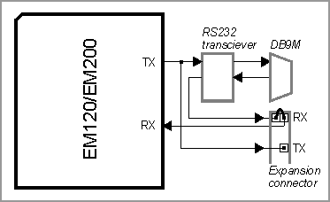
Output signals that are present both on the DB9M and expansion connectors (DTR, RTS, TX) need not be switched. For example, the TX (output) line from the attached EM120/EM200 is connected to the RS232 transceiver IC and to the expansion connector. For input signals (RX, CTS, DSR), there must be a way to disconnect the RS232 transceiver IC from the attached EM120/EM200. Three jumpers (combined with pins RX, CTS, and DSR of the expansion connector) serve this purpose.
For example, when the RX jumper is closed, the RX pin of the attached EM120/EM200 receives a signal from the RS232 transceiver. When the jumper is opened, you can use the RX pin on the expansion connector to supply a TTL RX signal from your own external board. The figure below illustrates this:
The maximum load for all CMOS-type lines (P0, P1, ... RX, TX...) is 10mA.