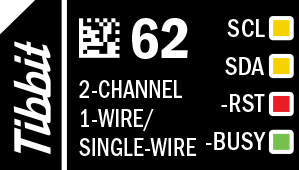
#62, M1T: Two 1-Wire/Single-Wire Ports

Function: Two 1-wire/single-wire ports
Form factor: M1T
Category: Input/output module
Special needs: ---
Power requirements: 5V/20mA (average, max. current may vary depending on the number and type of the sensors connected, and may reach 70mA)
Operating temperature range: –40°C to +85°C

Details
Tibbit #62 offers two 1-wire/single-wire ports supporting DS18B20-based 1-wire temperature sensors, as well as DHT11 and DHT22 single-wire temperature/humidity sensors. Each channel can be configured for 1-wire or single-wire operation. This Tibbit allows connecting up to sixteen 1-wire sensors per channel. Single-wire devices, by their nature, only allow one sensor per channel. The Tibbit's channel drivers were carefully designed to maximize the allowable cable lengths, thus enabling the data collection from sensors installed hundreds of meters away from the TPS host.
Control Lines and LED colors
Tibbit #62 has four control lines, each equipped with an LED:
- SCL (yellow LED) is the clock line of the I2C interface. The line is HIGH when idle. This Tibbit supports clock stretching, which is why the line is shown as bidirectional (and its LED is yellow).
- SDA (yellow LED) is the data line of the I2C interface. The line is HIGH when idle.
- –RST (red LED) is the module reset line, active LOW. Internally, this line is connected to the PIC microcontroller's reset pin. The line should be kept HIGH for normal Tibbit operation. Toggle the line LOW, then HIGH to reset the microcontroller. This line is also used for the reprogramming (in-system updates) of the PIC's firmware.
- –BUSY line (green LED), when LOW, indicates that the Tibbit is not ready to receive I2C commands. Poll this line before attempting I2C communications with the Tibbit.
IO Lines
Tibbit #62 has four IO lines:
- IO1 is the 5V output. It can supply up to 50mA of current to 1-wire and single-wire devices. This output is software-controlled and features an overcurrent and short-circuit protection.
- IO2 is the data line of the first channel. The channel is software-configurable for 1-wire or single-wire operation. In the 1-wire mode, you can connect up to sixteen 1-wire sensors. The single-wire specification permits only one sensor per channel.
- IO3 is the data line of the second channel; its specification is the same as that of the first channel.
- IO4 is a dedicated GND line that connects to the sensors' ground wires.
Typical Connection Diagrams for 1-Wire Sensors
1-wire temperature sensors are based on the DS18B20 digital thermometer IC. 1-Wire devices can operate using just two wires -- DQ (data) and GND (ground). In this arrangement, the sensors are powered through the DQ line, and no separate power line is necessary. This method of deriving power from the 1-wire bus is called "parasite power." It is also possible to power 1-wire devices through a dedicated power line called VDD. The diagrams below illustrate the two methods of connecting DS18B20-based sensors to Tibbit #62.
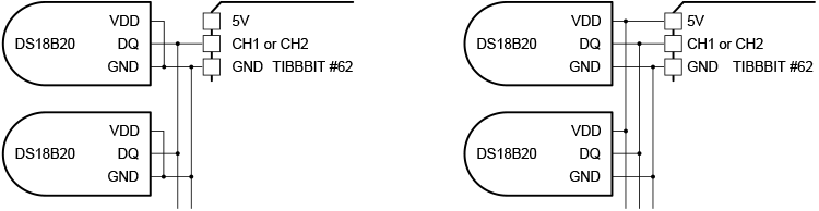
Left: Two-wire (parasite power) arrangement. Right: Three-wire (separate power) arrangement
When using a two-wire (parasite power) connection, connect each sensor's power (VDD) line to the ground (GND) line. We recommend using the three-wire (separate power) connection when:
- The wires are long
- There are multiple 1-wire sensors connected to the same channel (especially when using the star topology)
- The system operates in an environment with temperatures exceeding 100oC
The ability to connect multiple sensors to a single port and reliably work through long cables are significant advantages of 1-wire devices. To maximize acceptable cable lengths and reliability, Tibbit #62 was designed with MOSFET pull-up drivers on both channels. For best results, you will still need to consider the proper topology of your multi-sensor network.
To enable the longest distances, use the linear topology, in which 1-wire sensors are stringed together on a "bus." Many installations also use a star topology, where cables of multiple sensors are joined together at the Tibbit. This will work for modest cable lengths of 10-15 meters, but using a three-wire (separate power) wiring is always recommended.
The following application note contains much more information on the subject: https://pdfserv.maximintegrated.com/en/an/AN148.pdf.
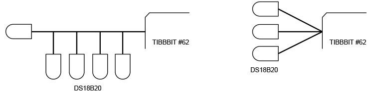
Left: Linear topology. Right: Star topology.
Connection Diagram for Single-Wire Sensors
Single-wire sensors, such as the DHT22 device, differ from 1-wire sensors in that:
- Only one single-wire sensor can be connected per Tibbit's channel -- single-wire devices are not addressable
- No parasite power arrangement is possible -- there is a separate power line, and it must be connected

Library and AppBlocks Support
Tibbit #62 is supported by a Tibbo BASIC library. The library includes the API calls for configuring the channels, discovering (enumerating) connected 1-wire sensors, and reading sensor data. The library can output temperature readings in degrees Celsius or Fahrenheit. You can find the library repository here: https://github.com/tibbotech/libraries/tree/main/tibbits/tbt62.
The use of the library is illustrated by the following Tibbo BASIC test program: https://github.com/tibbotech/CA-Test-Tibbit-62.
This Tibbit is also supported in AppBlocks, Tibbo's in-browser, no-code, flowchart-based application development platform. You can access the platform here: https://appblocks.io/.
 The following walkthrough video shows how to work with 1-wire and single-wire sensors in AppBlocks: https://www.youtube.com/watch?v=1rzGAGgJPlM&t=8s.
In-System Firmware Updates
The PIC microcontroller of Tibbit #62 can be upgraded in the system and without any additional hardware. The firmware update process utilizes the low-voltage programming (LVP) mode of the PIC microcontroller, with the SCL line acting as ICSPCLK, the SDA line acting as ICSPDAT, and the –RST line used to put the microcontroller into the LVP mode.
Tibbo provides a library for in-system upgrades; you can find it here: https://github.com/tibbotech/libraries/tree/main/pic.
Specifications
| Table #1 — Absolute Maximum Ratings | |
|
Supply voltage |
–10V to +5.5V |
|
CH1 or CH2 relative to GND |
–0.5V to +5.5V |
|
SCL, SDA, -RST, -BUSY lines |
–0.3V to +3.6V |
|
Operating temperature |
–40°C to +85°C |
| Table #1 — Electrical Characteristics | |
|
Input supply voltage |
4.5VDC to 5.5VDC |
|
Total current consumption |
20mA to 70mA |
|
Output current capability (IO1) |
50mA |
|
Nominal overcurrent detection range (IO1) |
50mA ~ 75mA |
|
Overcurrent detection nominal reaction time (IO1) |
100ms |
|
IO1 to GND short circuit detection time |
20ns |
|
SCL, SDA, -RST, -BUSY lines compatibility |
3.3V |
|
Operating temperature |
–40°C to +85°C |
|
ESD protection |
IO1 ~ IO4 are equipped with IEC 61000-4-2 standard-compatible TVS diodes |
| Table #1 — Serial Interface Characteristics | |
|
Interface type |
I2C |
|
Device address |
0x40 |
|
Frequency |
20kHz ~ 100kHz (100kHz recommended) |
|
Features |
Clock stretching enabled |