Resetting and Initializing the Onboard FPGA
For the correct operation of Tibbit #26, the FPGA IC must be properly reset and uploaded with the run-time binary code. As M1 Tibbits only have four CPU lines, implementing a dedicated reset line wasn't possible. As a result, the FPGA reset is generated by manipulating –CS and SCLK lines.
Here is the FPGA reset procedure (for reference, see tbt26_init() @ tbt26.tbs of the test_tibbit_26 project):
- Set the –CS line HIGH.
- Set the SCLK line LOW.
- Set the SCLK line HIGH. Now the FPGA is in reset.
- Generate a small delay (optional).
- Set the –CS line LOW.
- Set the SCLK line LOW.
- Set the SCLK line HIGH. Now the FPGA is out of reset.
If the above sounds cryptic, here is the schematic diagram of the reset circuit:
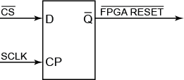
The circuit is based on a D trigger clocked by the SCLK line. The data input D of the trigger is connected to the –CS line. The FPGA's reset line (active LOW) is taken from the inverted output –Q of the trigger. Setting the –CS line HIGH and producing a rising edge on the SCLK line latches the trigger, and its –Q (inverted) output becomes LOW. The FPGA IC enters the reset state. To release the FPGA from reset, you need to set the –CS line LOW and produce another rising edge on the SCLK line.
Once the FPGA is out of reset, avoid toggling the SCLK line while the –CS line is HIGH (inactive). This shouldn't be problematic, as there is no point in generating SPI clocks while the chip select is not asserted.
Following reset, the FPGA must be uploaded with the run-time binary file (for reference, see tbt26_init() @ tbt26.tbs of the test_tibbit_26 project).
Key points:
- SPI mode 2 is used; bytes are transmitted most-significant bit (MSB) first.
- Bytes of the run-time binary (IR_Remote_bitmap.bin) are sent to the FPGA one after one.
- After the last byte has been sent, the program generates 50 additional clock cycles. We don't know why this is necessary; we just followed Lattice's specifications.
- After that, the success or failure of the upload procedure is verified through the DONE/MISO line.
As the name implies, the DONE/MISO line serves two functions. When the –CS line is asserted (LOW), the DONE/MISO line works as the standard MISO line of SPI. When the –CS line is HIGH, the DONE/MISO line channels the state of the FPGA's CDONE output. This output becomes HIGH if the upload of the binary file is successful.