TB1005 Test Board
 This is a legacy device. The following information is provided as it was documented originally, albeit with some corrections and changes for clarity and style.
The TB1005 test board is provided for the convenience of evaluating the DS1005 controller (IB1005 + SB1005 boards). The board is basically a loopback, feeding the relay outputs into the sensor inputs of the DS1004. The schematic diagram of the test board's connections is shown below:
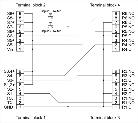
Relays 1~6 are wired into sensor inputs 1~6. They commutate "VIN", which is the voltage from the power source for the DS1005. When a relay is activated, this voltage is applied to a corresponding sensor input.
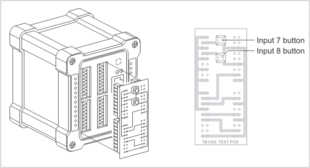
There are eight sensor inputs, but only six relays. The remaining sensor inputs, 7 and 8, are controlled by two buttons that play the same role as the relays. Push a button and a corresponding sensor input is triggered.