External LED Control
The NB1000 is intended to be used with the LB1000 board, which provides:
- A green and red LED pair
- A green and yellow LED pair
- An LED bar comprising five yellow LEDs
Green and Red LED Pair — System Status Indication
These LEDs are controlled by the SG and SR pins of the EM1000. Further information on status LEDs can be found in Status LEDs.
Green and yellow LED pair — Ethernet Status Indication
These LEDs are connected to the EG and EY lines of the EM1000 that control the green and yellow LEDs on the NB1000.
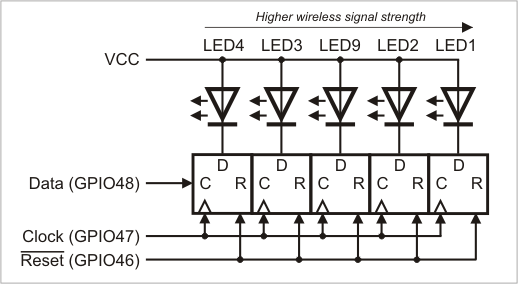
LED Bar — Wireless Signal Strength indication
These LEDs are controlled through three GPIO lines of the EM1000 — GPIO46, GPIO47, and GPIO48.
GPIO46 is the reset line of the LED bar. Clearing this line sets all five outputs to LOW, which turns all LEDs ON. GPIO47 is a clock line — a positive (LOW-to-HIGH) transition on this line "shifts in" the data on the GPIO48 line. The circuit that controls the LEDs is shown below. The LED numbers correspond to numbers shown in the LB100x drawing.
If you want to switch an LED ON, then set the data line LOW. The data bit for LED1 (indicating the highest signal strength) is clocked in first. That's the short explanation. In further detail, we can say:
- GPIO48 is the data line; set it to the state that you wish the LED to be in, LOW = ON, HIGH = OFF.
- When you then pull GPIO47 (Clock line) from its normal state (HIGH) to LOW and then back to HIGH, the state of the data line is read in and used for LED1.
- For example, if you want to turn on LED2, you have to set GPIO48 to LOW, toggle the clock once (HIGH-LOW-HIGH) to set LED1 ON, set GPIO48 to HIGH (because you want LED1 off) and then just toggle the clock again (HIGH-LOW-HIGH). At this point, the state of LED1 would shift to LED2 (so LED2 would light up).
So assuming that all LEDs are OFF and each row means that we have toggled through one clock cycle:
|
Clock cycle |
Data |
LED1 |
LED2 |
LED3 |
LED4 |
LED5 |
|
1 |
LOW |
ON |
OFF |
OFF |
OFF |
OFF |
|
2 |
LOW |
ON |
ON |
OFF |
OFF |
OFF |
|
3 |
HIGH |
OFF |
ON |
ON |
OFF |
OFF |
|
4 |
LOW |
ON |
OFF |
ON |
ON |
OFF |
|
5 |
HIGH |
OFF |
ON |
OFF |
ON |
ON |
As you can see, each clock cycle sets a new state for LED1 which directly corresponds to the state of the Data line, and shifts all previous LED states.