Detailed Device Info
I/O Pin Assignment
|
Pin # |
Function |
Description |
|
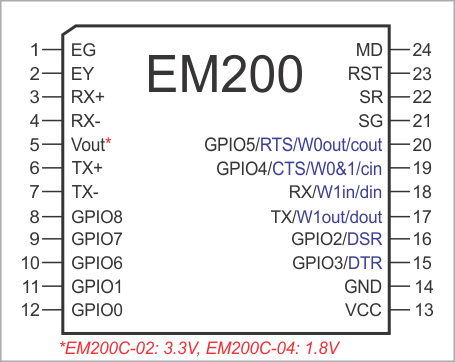
1 |
EG |
Green Ethernet status LED control line. |
|
2 |
EY |
Yellow Ethernet status LED control line. |
|
3 |
RX+ |
Ethernet port, positive line of the differential input signal pair. |
|
4 |
RX– |
Ethernet port, negative line of the differential input signal pair. |
|
5 |
Vout |
"Clean" power for the magnetics circuitry: EM200C-02 devices: 3.3V EM200C-04 devices: 1.8V |
|
6 |
TX+ |
Ethernet port, positive line of the differential output signal pair. |
|
7 |
TX– |
Ethernet port, negative line of the differential output signal pair. |
|
8 |
GPIO8 |
General-purpose I/O line 8. |
|
9 |
GPIO7 |
General-purpose I/O line 7. |
|
10 |
GPIO6 |
General-purpose I/O line 6. |
|
11 |
GPIO1 |
General-purpose I/O line 1. |
|
12 |
GPIO0 |
General-purpose I/O line 0. |
|
13 |
VCC |
Positive power input, 5V nominal, ±5%, max. current consumption 50mA |
|
14 |
GND |
System ground. |
|
15 |
GPIO3/DTR |
General-purpose I/O line 3; conventionally also DTR output line of the serial port. |
|
16 |
GPIO2/DSR |
General-purpose I/O line 2; conventionally also DSR output line of the serial port. |
|
17 |
TX/W1out/dout |
TX, W1, and dout output of the serial port. |
|
18 |
RX/W1in/din |
RX, W1, and din input of the serial port. |
|
19 |
GPIO4/CTS/W0&1in/cin |
General-purpose I/O line 4; also CTS, W0&1, and cin input of the serial port. |
|
20 |
GPIO5/RTS/W0out/cout |
General-purpose I/O line 5; also RTS, W0, and cout output of the serial port. |
|
21 |
SG |
Green status LED control line. |
|
22 |
SR |
Red status LED control line. |
|
23 |
RST |
Reset line, active high. |
|
24 |
MD |
Mode selection pin. |
Additional Resources
The information on various hardware faculties of the EM200 can be found in the following topics:
- Serial Port and General-Purpose I/O Lines
- Ethernet Port Lines
- Flash Memory and EEPROM
- LED Lines
- Power, Reset, and Mode Selection Lines