LEDs
Each Tibbo Project PCB (TPP) is equipped with eight onboard LEDs:
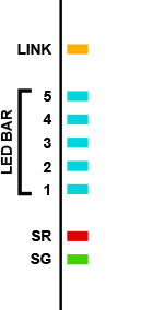
- Our standard green and red status LEDs.
- A single Ethernet status LED — the yellow "link" LED. See Status LEDs (LED Control Lines) for more information.
- Five blue LEDs forming an LED bar.
The Size 3 Linux Tibbo Project PCB (LTPP3), Gen. 2 has an additional four LEDs: one yellow link and one green activity LED for each of its two Ethernet ports. However, these LEDs are not visible when the board is installed in the Size 3 Linux Tibbo Project Box (LTPB3).
Blue LED Bar
Five blue LEDs form an LED bar. They are intended primarily for the indication of RF signal strength (i.e., Wi-Fi signal). These LEDs are controlled through three general-purpose I/O (GPIO) lines: 46, 47, 48.
GPIO46 is the reset line of the LED bar. Clearing this line sets all five outputs LOW and turns all LEDs ON. GPIO47 is a clock line — a positive (LOW-to-HIGH) transition on this line "shifts in" the data on the data line. The LED control circuit is shown below.
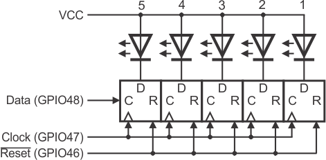
If you want to switch an LED ON, set the corresponding data line LOW. In the following example, we set the LEDs like this:
|
LED #5 |
LED #4 |
LED #3 |
LED #2 |
LED #1 |
|
OFF |
ON |
OFF |
ON |
ON |
Assuming all the LEDs were off previously (shown in gray), these are our steps. Each step represents one cycle of the clock line (HIGH-LOW-HIGH):
|
Clock |
Data |
LED #5 |
LED #4 |
LED #3 |
LED #2 |
LED #1 |
|
1 |
LOW |
ON |
OFF |
OFF |
OFF |
OFF |
|
2 |
LOW |
ON |
ON |
OFF |
OFF |
OFF |
|
3 |
HIGH |
OFF |
ON |
ON |
OFF |
OFF |
|
4 |
LOW |
ON |
OFF |
ON |
ON |
OFF |
|
5 |
HIGH |
OFF |
ON |
OFF |
ON |
ON |
The reset line is not really necessary. You can be certain what pattern is displayed by the LEDs for as long as you generate five clock cycles every time you send new data into this circuit.
TiOS-Based TPPs
Here is our library code for controlling the LED bar on the TPP2, TPP3, TPP2(G2), TPP3(G2) and TPP2(G3):
sub on_sys_init
...
   'enable the control lines (notice that the use of the RST line is not really necessary)
   io.num=PL_IO_NUM_46
   io.enabled=YES
   io.num=PL_IO_NUM_47
   io.enabled=YES
   io.num=PL_IO_NUM_48
   io.enabled=YES

   signal_strength_set(0) 'this will turn all 5 LEDs OFF
...
end sub

sub signal_strength_set(strength as byte)
'Bits 0-5 of strength argument correspond to LEDs (bit5 is for the LED #5, bit0 -- for LED #0)

   dim f,x as byte
   dim s as string(8)

   s=mid(bin(strength),3,8)
   s=strgen(8-len(s),"0")+s

   'make 5 clocks
   io.num=PL_IO_NUM_47
   for f=0 to 4
      x=1-val(mid(s,f+4,1))
      io.lineset(PL_IO_NUM_48,x)
      io.state=LOW
      io.state=HIGH
   next f
end sub
LTPP3(G2)
Requires toggling the GPIO lines manually.