Implemented Configurations
At the moment, there is only one use for Tibbit #57:
Smart LED Controller Configuration
In the smart LED configuration, Tibbit #57 can control a string of daisy-chained SK6812RGBW LEDs. SK6812RGBW devices carry a small IC driving four onboard light emitters with red, green, blue, and white colors. Each of the color sources can be set to one of 256 levels of brightness, meaning that four bytes of data are needed per LED.
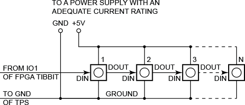
Smart LEDs are controlled via a special one-wire protocol. Each LED has DIN (data in) and DOUT (data out) pins. The DIN pin of the first LED in the chain is connected to the IO1 line of the FPGA Tibbit. The DOUT of the first LED is connected to the DIN of the second LED, the DOUT of the second LED — to the DIN of the third LED, and so on.
In the smart LED configuration, the FPGA receives the data from the CPU via SPI and stores this data in the 8,192-byte data buffer.
As with all SPI communications, transactions start when the –CS line goes LOW and end when the –CS line goes HIGH. Bringing the –CS line LOW clears the memory buffer of the FPGA and resets the buffer pointer to 0 (the first buffer location). Each subsequent byte of data sent in the course of an SPI transaction is stored into the buffer location pointed at by the buffer, and then the pointer is incremented by one. Once the –CS line goes HIGH, the FPGA starts sending the data stored in its buffer memory to the LED chain.
The DONE signal (which is multiplexed with the MISO line) is asserted LOW for the duration of the LED update cycle, meaning that DONE goes LOW as soon as –CS goes HIGH. The DONE signal goes HIGH once the LED update cycle is completed. To query the state of the DONE signal, read the DONE/MISO line while the –CS line is HIGH.
A new SPI transaction should not start while the DONE signal is LOW.
Data Format for SPI Write Transactions
|
Byte number |
MOSI |
MISO |
|
1 |
Green level, LED N* |
--- |
|
2 |
Red level, LED N |
--- |
|
3 |
Blue level, LED N |
--- |
|
4 |
White level, LED N |
--- |
|
5 |
Green level, LED N-1 |
--- |
|
6 |
Red level, LED N-1 |
--- |
|
7 |
Blue level, LED N-1 |
--- |
|
8 |
White level, LED N-1 |
--- |
|
--- |
--- |
--- |
|
Green level, LED 2 |
--- |
|
|
Red level, LED 2 |
--- |
|
|
Blue level, LED 2 |
--- |
|
|
White level, LED 2 |
--- |
|
|
Green level, LED 1 |
--- |
|
|
Red level, LED 1 |
--- |
|
|
Blue level, LED 1 |
--- |
|
|
White level, LED 1 |
--- |
* LED numbers (N, 2, 1) correspond to numbers on the diagram above.
Data Format for SPI Read Transactions
No read transactions are supported in this configuration.
Sample Project
The use of this and other "I²C/SPI" Tibbits is illustrated by a group of Tibbo BASIC test projects. You can find them at http://tibbo.com/basic/resources/i2c_tibbits.html. The smart LED project is titled test_tibbit_57_sled.