TB1000 Terminal Block Adapter
 This is a legacy device. The following information is provided as it was documented originally, albeit with some corrections and changes for clarity and style.
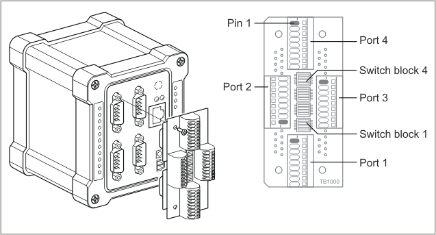
The TB1000 Terminal Block Adapter is designed to be used with DS1000, DS1002, and DS1003 devices (or IB1000, IB1002, and IB1003 boards). This adapter "converts" the DB9 connectors of the DS1000, DS1002, and DS1003 into nine-terminal blocks of the "spring clamp" type. These are convenient for attaching wires, which is very useful for industrial installations.
Each terminal of the terminal block connects directly to a pin on the DB9 connector. Pin numbers on DB9 connectors and terminal blocks match exactly. Therefore, the terminal assignment on each terminal block is as follows:
|
Terminal |
RS232 mode |
RS422 mode |
RS485 mode |
|
#1 |
--- |
RTS– (output) |
--- |
|
#2 |
RX (input) |
RX– (input) |
RX– (input) |
|
#3 |
TX (output) |
TX+ (output) |
TX+ (output) |
|
#4 |
DTR (output) |
TX– (output) |
TX– (output) |
|
#5 |
SYSTEM GROUND |
SYSTEM GROUND |
SYSTEM GROUND |
|
#6 |
DSR (input) |
RX+ (input) |
RX+ (input) |
|
#7 |
RTS (output) |
RTS+ (output) |
--- |
|
#8 |
CTS (input) |
CTS+ (input) |
--- |
|
#9 |
--- |
CTS– (input) |
--- |
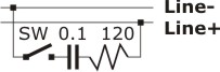
DS1002 and DS1003 devices have universal serial ports that can additionally work in the RS422 and RS485 modes. Proper signal termination may be required when longer cables are used in these modes. The TB1000 has four switch blocks, one for each port. Each switch block includes four switches. When closed, each switch connects a termination circuit between the "+" and "–" signals in a signal pair:
|
Switch # within the block |
Signal pair |
|
1 |
CTS+/CTS– |
|
2 |
RTS+/RTS– |
|
3 |
RX+/RX– |
|
4 |
TX+/TX– |
The TB1000 can additionally be secured on a DS10xx device using four screws (included). This terminal block adapter is also compatible with the "secondary cover," also known as the "waterproof cover."