Wiegand Mode
In the Wiegand mode, the serial port is able to receive the data directly from any Wiegand device, such as a card reader, and also output the data in the Wiegand format, as if it was a card reader itself. The Wiegand interface is popular in the security, access control, and automation industry.
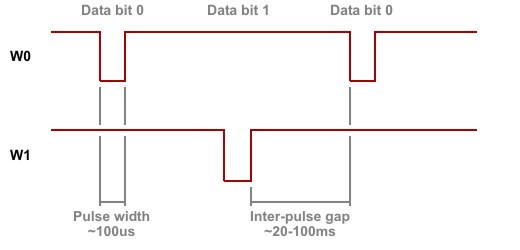
Standard Wiegand data transmission is shown below. There are two data lines: W0 and W1. A negative pulse on the W0 line represents data bit 0. A negative pulse on the W1 line represents data bit 1. There is no standard Wiegand timing, so pulse widths, as well as inter-gap widths, vary greatly between devices. On average, the pulse width is usually in the vicinity of 100µs (microseconds), while the inter-pulse gap is usually around 20ms~100ms (milliseconds).
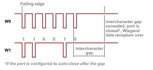
There is no explicit way to indicate the end of transmission. The receiving device either counts received bits (if it knows how many to expect) or assumes the transmission to be over when the time since the last pulse on the W0 or W1 line exceeds a certain threshold; for example, 10 times the expected inter-pulse gap.
The serial port outputs Wiegand data through the W0out and W1out lines and receives data via the W0&1in and W1in lines. "W0&1in" means that the signal on this input must be a logical AND of the W0 and W1 output lines of an attached Wiegand device (see below for details). Your application should not attempt to work with W0out and W1out outputs directly through the io. object when the serial port is in the Wiegand mode.
 Please remember that depending on the platform, you may be required to configure some or all of your serial port's lines as inputs or outputs through the io.enabled property of the io. object. Additionally, you may have the freedom of remapping certain serial port lines to different I/O pins of the device if required. For more information, refer to your device's platform documentation (for example, the EM1000's is here).
How the Serial Port Sends and Receives Raw Wiegand Data
There are many Wiegand data formats currently in use. These formats define how "raw" data bits are processed and converted into actual data. Typically, there are two parity bits — one at the beginning and another one at the end of Wiegand data. Parity calculation, however, varies from format to format. Additionally, the length of Wiegand output is not standardized.
All this makes it impossible for the ser. object to verify incoming Wiegand data (i.e., check the data length and calculate the checksum). Instead, this task is delegated to your application while the ser. object only receives raw data. Similarly, before sending out Wiegand data, your application needs to prepare this data in the desired format — the ser. object will output any data stream.
How the Wiegand Data Is Stored in the RX and TX Buffers of the Serial Port
When in the Wiegand mode, each data byte in the TX or RX buffer of the serial port represents one bit of Wiegand data. This bit is recorded in the least significant bit position of each data byte in the buffer. For your application's convenience, when the serial port receives a Wiegand bit stream, it adds an offset of 30Hex to each data bit. Therefore, the data recorded into the RX buffer can only consist of bytes 30H and 31H (these correspond to ASCII characters "0" and "1"). This way, when your application reads the RX buffer's contents into a string variable, the data will be "readable" without any additional conversion (ASCII characters with codes "0" and "1" would not be "readable").
When the serial port outputs Wiegand data, it only takes bit 0 of each byte in the TX buffer. Other bits can contain any data. You can, for instance, put a string of ASCII characters "0" and "1" into the TX buffer and these will be correctly interpreted as data bits 0 and 1. This, again, is convenient for your Tibbo BASIC/C application.
How the Serial Port Transmits Wiegand Data
Wiegand data output timing is fixed and your application cannot change it. Data pulses are 100µs wide and inter-pulse gaps are 2ms wide.
How the Serial Port Receives Wiegand Data
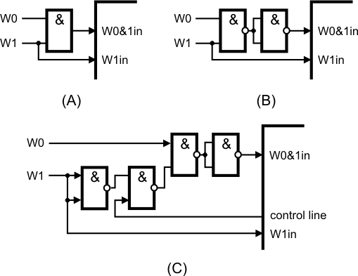
You already know that the W0&1in input of the serial port must receive a logical AND of W0 and W1 output of an attached Wiegand device. A simple AND gate will do the job (figure A below). Actually, NOR-AND gates are more popular and these can be used too (figure B). In case you are building a product that will also accept clock/data input, you may need to control whether the W0&1in input should receive a logical AND of two lines or just one of the lines. Schematic diagram C uses an additional I/O line of the device to control this. When the control line is HIGH, the W0&1in input receives a logical AND of both W0 and W1 lines. When the control line is LOW, the W0&1in input receives just the signal from the W0 line. Four gates are required for this, so you will get away with using a single 74HC00 IC.
The serial port does not require an incoming Wiegand data stream to adhere to any strict timing. The port is simply registering HIGH-to-LOW transitions on the W0&1in line. When such a transition is detected, the port checks the state of the W1 line. If the line is HIGH, data bit 0 is registered; when the line is low, data bit 1 is registered.
The end of a Wiegand transmission is identified by timeout — the serial port has a special property for that, called "intercharacter delay" (see Serial Settings). Another property — "auto-close" — can be used to disable the serial port after the delay has been encountered. This way, when the Wiegand output is over, the port will be disabled and no further data will enter the port until you re-enable it.