Clock/Data Mode
In the clock/data mode, the serial port is able to receive the data directly from any clock/data or "magstripe interface" device, such as a card reader. The serial port is also able to output data in the clock/data format, as if it was the card reader itself. Magstripe and clock/data interfaces are popular in the security, access control, automation, and banking industry.
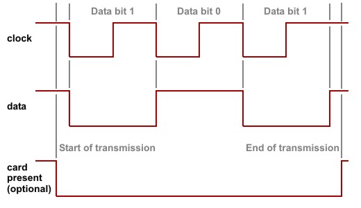
Standard clock/data transmission is shown below. There are two data lines: clock and data. Each negative transition on the clock line marks the beginning of the data bit. The data line carries the actual data. When the state of the data line is LOW, it means data bit 1 and vice versa. There is no standard clock/data timing and some devices, such as non-motorized magnetic card readers, output the data at variable speeds (depending on how fast the user actually swipes the card).
The magstripe interface only differs from the clock/data interface in that it has a third line: card present. This line goes LOW before the data transmission and goes back to HIGH after the transmission is over. The serial port does not require the card present line for data reception. Just like with Wiegand data, it identifies the end of incoming data by measuring the time since the last negative transition on the clock line. For data transmission, your Tibbo BASIC/C application can easily use any regular I/O line to serve as card present line.
Compared to the Wiegand interface, the data format of clock/data interface is very standardized and its varieties include standard data formats for different "tracks" of the magnetic card. Most clock/data devices you will actually encounter have nothing to do with magnetic cards, but the terminology persists.
The serial port outputs clock/data signals through the cout and dout lines and receives data via the cin and din lines. Your application should not attempt to work with cout and dout outputs directly through the io. object when the serial port is in the clock/data mode.
 Please remember that depending on the platform, you may be required to configure some or all of your serial port's lines as inputs or outputs through the io.enabled property of the io. object. Additionally, you may have the freedom of remapping certain serial port lines to different I/O pins of the device if required. For more information, refer to your device's platform documentation (for example, the EM1000's is here).
How the Serial Port Sends and Receives Raw Clock/Data Data
Clock/data from different "tracks" have different encoding. Encoding defines how "raw" data bits are processed and converted into actual data. To allow maximum flexibility, and also to maintain the data processing style used by the Wiegand interface, the serial port leaves the task of converting between the raw and actual data to your application. The serial port only sends and receives raw data without checking or transforming its contents.
How the Clock/Data Stream is Stored in the RX and TX buffers of the Serial Port
When in the clock/data mode, each data byte in the TX or RX buffer of the serial port represents one bit of the clock/data stream. This bit is recorded in the least significant bit position of each data byte in the buffer. For your application's convenience, when the serial port receives clock/data bit stream, it adds an offset of 30Hex to each data bit. Therefore, the data recorded into the RX buffer can only consist of bytes 30H and 31H (these correspond to ASCII characters "0" and "1"). This way, when your application reads the RX buffer's contents into a string variable, the data will be "readable" without any additional conversion (ASCII characters with codes "0" and "1" would not be "readable").
When the serial port outputs clock/data stream, it only takes bit 0 of each byte in the TX buffer. Other bits can contain any data. You can, for instance, put a string of ASCII characters "0" and "1" into the TX buffer and these will be correctly interpreted as data bits 0 and 1. This, again, is convenient for your Tibbo BASIC/C application.
How the Serial Port Transmits Clock/Data Stream
Clock/data output timing is fixed and your application cannot change it. The data is output at a rate of 400µs/bit (both LOW and HIGH phases of the clock signal are 200µs in length).
How the Serial Port Receives Clock/Data Stream
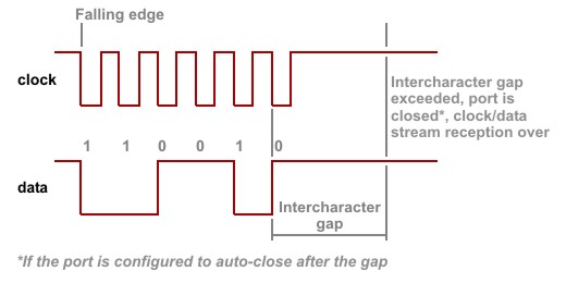
The serial port does not require an incoming clock/data stream to adhere to any strict timing. The port is simply registering HIGH-to-LOW transitions on the clock line. When such a transition is detected, the port checks the state of the data line. If the line is HIGH, data bit 0 is registered; when the line is low, data bit 1 is registered.
The end of clock/data transmission is identified by timeout — the serial port has a special property for that, called "intercharacter delay" (see Serial Settings). Another property — "auto-close" — can be used to disable the serial port after the delay has been encountered. This way, when the clock/data output is over, the port will be disabled and no further data will enter the port until you re-enable it.