EM500EV-MB0

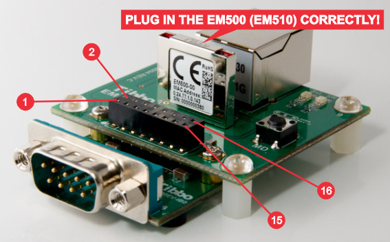
The EM500EV-MB0 incorporates a socket for inserting an EM500 or EM510 IoT module.
 It is physically possible to plug an EM500 or EM510 into the EM500EV-MB0 incorrectly. Doing so may irreparably damage the module.
Only plug the EM500 or EM510 as shown in the photograph above.
The EM500EV-MB0 also features the following:
- A power jack and a switching regulator with 3.3V output. This 3.3V power is supplied to the EM500 or EM510 and is also provided on the interface board connector (see below).
- An MD button, which is connected to the MD input of the EM500 or EM510.
- Green and red status LEDs.
- A two-row interface board connector.
Interface Board (IB) Connector
|
Pin # |
Function |
|
1 |
VCC output (3.3V) |
|
2 |
GND |
|
3 |
RX* |
|
4 |
TX* |
|
5 |
GPIO0/P0.0/INT0* |
|
6 |
GPIO1/P0.1/INT1* |
|
7 |
GPIO2/P0.2* |
|
8 |
GPIO3/P0.3* |
|
9 |
GPIO4/P0.4* |
|
10 |
GPIO5/P0.5* |
|
11 |
GPIO6/P0.6* |
|
12 |
GPIO7/P0.7* |
|
13 |
MD* |
|
14 |
RST* |
|
15 |
GND |
|
16 |
VIN (12V) |
* Directly connected to the corresponding pin of the EM500/EM510.
