EM500EV-IB1
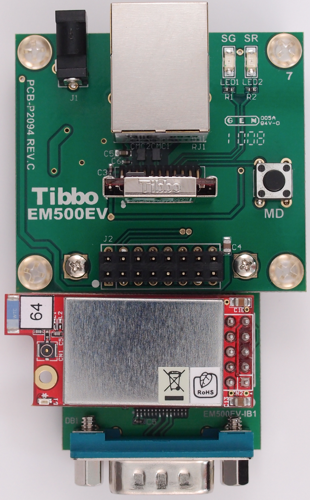
The EM500EV-G development system (featuring the IB1 interface board).
Note the orientation of the GA1000.
The EM500EV-IB1 features a connector for the GA1000 Wi-Fi add-on module, 1,024KB of flash memory, and a serial port with limited functionality (RX, TX, CTS, and RTS lines only).
Connection to the GA1000 is implemented according to schematic diagram C presented in Connecting GA1000 to Tibbo Devices. Note that the GA1000 is only supported by the EM500.
Connection to the flash memory is implemented according to the schematic diagram presented in Flash Memory and EEPROM (of the EM500 documentation).
The RS232 interface lines are available on a standard DB9M connector:

|
Pin # (DB9M) |
R232 line (DB9M) |
EM500 control line |
|
1 |
--- |
--- |
|
2 |
RX (input) |
RX |
|
3 |
TX (output) |
TX |
|
4 |
--- |
--- |
|
5 |
SYSTEM GROUND |
|
|
6 |
--- |
--- |
|
7 |
RTS (output) |
GPIO2/P0.2 |
|
8 |
CTS (input) |
GPIO0/P0.0/INT0 |
|
9 |
--- |