Serial Port and General-Purpose I/O Lines
Pin Functions and Descriptions
|
Pin Number |
Signal Name |
Direction |
Description |
|
Main conn., #3 |
P3 DTR* |
Input/output Output |
General-purpose input/output line Data terminal ready output |
|
Main conn., #4 |
P2 DSR* |
Input/output Input |
General-purpose input/output line Data set ready input |
|
Main conn., #9 |
RX |
|
Serial receive line |
|
Main conn., #10 |
TX |
|
Serial transmit line |
|
Main conn., #11 |
P4 CTS/SEL* |
Input/output Input |
General-purpose input/output line Clear to send input; full-/half-duplex selection input |
|
Main conn., #12 |
P5 RTS/DIR* |
Input/output Output |
General-purpose input/output line Request to send output (full-duplex mode); data direction control output (half-duplex mode) |
* Implemented in (supported through) firmware.
Line functions defined by the Application Firmware are shown in blue.
Features and I/O Line Characteristics
The EM203 module includes a serial port (RX and TX lines) and several general-purpose I/O lines: P2–P5. Note that there are no P0 or P1 lines; this naming convention ensures compatibility with the EM100. All the lines mentioned are CMOS-type and can function as inputs or outputs from a hardware perspective. Each I/O line has a maximum load current of 10mA.
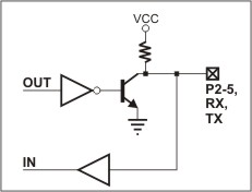
The simplified structure of the EM203's I/O lines is depicted in the circuit diagram below. These lines are quasi-bidirectional, resembling open-collector outputs with weak pull-up resistors. They lack explicit direction control. To read an external signal applied to a pin, the corresponding OUT line must first be set to HIGH. It is safe to drive the pin LOW externally while it outputs HIGH internally.

Serial-to-Ethernet Firmware Integration
The EM203’s serial-to-Ethernet firmware maps certain serial port functions to the general-purpose I/O lines. These functions, shown in blue in the table above, allow specific configurations based on application needs. For instance, P5 serves as a universal input/output pin but can also act as the RTS (Ready to Send) output of the serial port, depending on the firmware settings. Consequently, P5 can be viewed either as a general-purpose I/O line or as a specific serial port control line.
CMOS-Type Compatibility
As a CMOS device, the EM203's serial port and I/O lines can be directly connected to the corresponding pins of most microcontrollers or microprocessors.
To connect the EM203 to a "true" serial port (e.g., the COM port of a PC), you must add an external interface IC, such as:
- MAX232 for RS232.
- MAX485 for RS485.
Logical Signal Behavior
The logical signals on the EM203's serial port lines are active LOW and behave as follows:
- TX and RX lines:
- HIGH when idle.
- LOW for the start bit.
- HIGH for the stop bit.
- CTS and RTS lines:
- LOW indicates "transmission allowed."
- HIGH indicates "transmission not allowed."
These signaling conventions are standard for CMOS-level serial ports and are the opposite of RS232 signaling. The inversion occurs because interface ICs (e.g., MAX232) also invert the signals internally.
