Ethernet Port Lines
The Ethernet port of the EM2000 is of the 10/100BaseT type. Onboard electronics of the EM2000 do not include Ethernet magnetics, so the magnetics circuitry must be connected externally (to the TX+, TX–, RX+, and RX– pins).
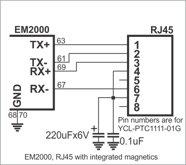
You can use either a standalone magnetics part (such as YCL-PH163112) or an RJ45 connector with integrated magnetics (e.g., YCL-PTC1111-01G). Here is the circuit diagram based on the YCL-PTC1111-01G:
It is important to make the PCB traces interconnecting the Ethernet port pins of the EM2000 and external magnetics circuitry as short as possible. Making the traces too long may cause the noise level generated by your PCB to surpass the maximum radiated emission limits stipulated by FCC/CE regulations. Additionally, longer Ethernet lines on the PCB will decrease the performance of your Ethernet port.
Note that the EM2000 has an onboard Ethernet link LED (yellow), as well as two Ethernet status LED control lines.
Using the EM2000 With Host Boards Designed for the EM1000
The EM2000 will work with boards designed for our EM1000 module. The circuit diagram for attaching Ethernet magnetics to the EM1000 is slightly different. Specifically, the EM1000 has AVCC lines, while the EM2000 does not. Pins 62 and 65, which used to be AVCC pins on the EM1000, are left unconnected on the EM2000 (so it is OK if your board has these lines).