Ethernet Port Lines
 There are two different Ethernet magnetics arrangements: one for original EM1000-...-00 and another for the EM1000-...-01/-02.
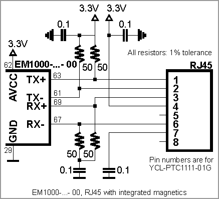
The Ethernet port of the EM1000 is of the 10/100BaseT type. The onboard electronics of the EM1000 do not include Ethernet magnetics, so magnetics circuitry must be connected externally to the TX+, TX–, RX+, RX–, and AVCC. The AVCC pin outputs clean power for the magnetics circuitry, which is very sensitive to noise. The voltage on the AVCC pin depends on the EM1000 version: 3.3V for -00 and 2.5V for the -01/-02. Separate AGND analog ground pins have been added on the -01/-02 versions. For the -00 version, there is no separate analog ground. Please note the following:
- The AVCC pin is an output!
- Do not combine AVCC with the VCC (main power) pin. On the -00 this is counter-productive and on the -01/-02 this will apply the wrong voltage to the AVCC pin. Doing so doesn't appear to cause immediate permanent damage to the -01/-02 versions, but the circuit will not work and the effects of prolonged over-voltage on the AVCC line are not known.
You can use either a standalone magnetics part (such as YCL-PH163112) or an RJ45 connector with integrated magnetics (i.e., YCL-PTC1111-01G). Here are two connection diagrams based on the YCL-PTC1111-01G — one for the -00 and another for the -01/-02.

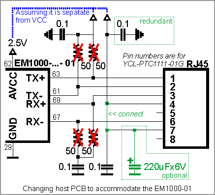
Once again, the -00 is a legacy part that has been replaced with the -01/-02. In case you have already made the PCB based on the -00 specifications and are not willing to change it, you can easily modify it to accommodate the -01/-02 (see diagram below):
- Do not install four 50Ω resistors (they are crossed out on the diagram).
- Connect a wire between pins 4 and 7 of the RJ45 connector (pin numbers are for YCL-PTC1111-01G).
- If possible, find a way to install a 220µF capacitor. The circuit will still work even if you don't have this capacitor, but you may have FCC/CE certification issues.
- Notice that one of the 0.1 capacitors becomes redundant, but that's OK.
- All of the above is based on the assumption that your host PCB was designed correctly and the AVCC output of the EM1000 is not joined together with the main VCC line. If you erroneously had AVCC and VCC combined together, then you will need to separate them as well: The AVCC pin outputs 2.5V on the -01/-02 versions and this is different from the main power on the VCC pin, which is 3.3V. Applying 3.3V to the AVCC pin of the -01/-02 versions doesn't appear to cause immediate permanent damage to the device, but the circuit will not work and the effects of prolonged over-voltage on the AVCC line are not known.
It is important to make the PCB wire connections between the Ethernet port pins of the EM1000 and external magnetics circuitry as short as possible. Making the wires too long may cause the noise level generated by your PCB to surpass the maximum radiated emission limits stipulated by FCC/CE regulations. Additionally, longer Ethernet lines on the PCB will make your board more susceptible to damage from electrostatic discharge (ESD).
The EM1000 also has two Ethernet status LED control lines.