Detailed Device Info
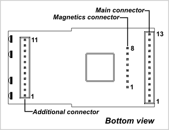
The EM1206 has three connectors: main connector, additional connector, and magnetics connector. Depending on the EM1206 version, the magnetics connector can be soldered facing up or down, as described in the Mechanical Dimensions topic.
Main Connector
|
Pin # |
Function |
Description |
|
1 |
VCCB |
Backup power for the real-time counter. Do not connect to 3.3V directly! |
|
2 |
MD |
Mode selection pin. |
|
3 |
RST |
Reset line, active high. |
|
4(1,2,3) |
GPIO5/P0.5/TX2/INT5 |
General-purpose I/O line 5 (P0.5); TX, W1, dout output of the serial port 2; Interrupt line 5. |
|
5(1,2,3) |
GPIO4/P0.4/RX2/INT4 |
General-purpose I/O line 4 (P0.4); RX, W1, din input of the serial port 2; Interrupt line 4. |
|
6(1,2,3) |
GPIO6/P0.6/RX3/INT6 |
General-purpose I/O line 6 (P0.6); RX, W1, din input of the serial port 3; Interrupt line 6. |
|
7(1,2,3) |
GPIO7/P0.7/TX3/INT7 |
General-purpose I/O line 7 (P0.7); TX, W1, dout output of the serial port 3; Interrupt line 7. |
|
8 |
VCC |
Positive power input, 3.3V nominal, ±5%, max. current consumption 230mA (100BaseT, PLL on). |
|
9 |
GND |
System ground. |
|
10(1,2,3) |
GPIO0/P0.0/RX0/INT0 |
General-purpose I/O line 0 (P0.0); RX, W1, din input of the serial port 0; Interrupt line 0. |
|
11(1,2,3) |
GPIO1/P0.1/TX0/INT1 |
General-purpose I/O line 1 (P0.1); TX, W1, dout output of the serial port 0; Interrupt line 1. |
|
12(1,2,3) |
GPIO2/P0.2/RX1/INT2 |
General-purpose I/O line 2 (P0.2); RX, W1, din input of the serial port 1; Interrupt line 2. |
|
13(1,2,3) |
GPIO3/P0.3/TX1/INT3 |
General-purpose I/O line 3 (P0.3); TX, W1, dout output of the serial port 1; Interrupt line 3. |
- This line is 5V-tolerant and can be interfaced to 5V CMOS devices directly.
- This line can serve as an RTS/Wout/cout line of a serial port (provided that this does not interfere with any other function).
- This line can serve as a CTS/W0&1in/cin line of a serial port (provided that this does not interfere with any other function).
Additional Connector
|
Pin # |
Function |
Description |
|
1 |
SG |
Green status LED control line. |
|
2 |
SR |
Red status LED control line. |
|
3(1,2) |
GPIO16/CO |
General-purpose I/O line 16 (does not belong to any port); square wave output line. |
|
4(1,2) |
GPIO8/P1.0 |
General-purpose I/O line 8 (P1.0). |
|
5(1,2) |
GPIO9/P1.1 |
General-purpose I/O line 9 (P1.1). |
|
6(1,2) |
GPIO10/P1.2 |
General-purpose I/O line 10 (P1.2). |
|
7(1,2) |
GPIO11/P1.3 |
General-purpose I/O line 11 (P1.3). |
|
8(1,2) |
GPIO12/P1.4 |
General-purpose I/O line 12 (P1.4). |
|
9(1,2) |
GPIO13/P1.5 |
General-purpose I/O line 13 (P1.5). |
|
10(1,2) |
GPIO14/P1.6 |
General-purpose I/O line 14 (P1.6). |
|
11(1,2) |
GPIO15/P1.7 |
General-purpose I/O line 15 (P1.7). |
- This line is 5V-tolerant and can be interfaced to 5V CMOS devices directly.
- This line can be assigned to serve as an RTS/Wout/cout line of a serial port.
Magnetics Connector
|
Pin # |
Function |
Description |
|
1 |
RX+ |
Ethernet port, positive line of the differential input signal pair. |
|
2 |
RX– |
Ethernet port, negative line of the differential input signal pair. |
|
3 |
AVCC |
"Clean" 1.8V power output for magnetics circuitry. |
|
4 |
--- |
--- |
|
5 |
--- |
--- |
|
6 |
AGND |
Analog ground. |
|
7 |
TX+ |
Ethernet port, positive line of the differential output signal pair. |
|
8 |
TX– |
Ethernet port, negative line of the differential output signal pair. |
Additional Resources
See these topics for more information on various hardware facilities of the EM1206:
- General-Purpose I/O Lines
- Ethernet Port Lines
- Serial Ports
- Square Wave Generator
- Flash Memory and EEPROM
- Real-Time Counter
- LED Lines
- Power, Reset, and Mode Selection Lines