DS1102
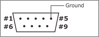
The DS1102 features a multimode, multichannel RS232/422/485 port. Physically, the port is implemented as a single DB9M connector.
Note: See Definition of RS422 and RS485 Modes for information on how these modes are implemented on the DS1102.
Port Pin Assignment
In the RS232 mode, the serial port of the DS1102 has three output and three input lines. In the RS422 mode, you get two output and two input line pairs. The RS485 mode offers one output line pair and one input line pair. These are not independent — they operate in the half-duplex mode.
Internally, the DS1102 has three independent serial ports. These are controlled through the ser. object.
Each of those ports has its own TX and RX lines. These lines are implemented in hardware and can't be "remapped." The following table shows how these RX and TX lines are connected to the DB9M:
|
RS232 |
RS422 |
RS485 |
|
|
#1 |
<No connection> |
TX2– (output, commonly RTS-) |
<No connection> |
|
#2 |
RX (input) |
RX– (input) |
RX– (input) |
|
#3 |
TX (output) |
TX+ (output) |
TX+ (output) |
|
#4 |
TX3 (output, commonly DTR) |
TX– (output) |
TX– (output) |
|
#5 |
Ground |
Ground |
Ground |
|
#6 |
RX3 (input, commonly DSR) |
RX+ (input) |
RX+ (input) |
|
#7 |
TX2 (output, commonly RTS) |
TX2+ (output, commonly RTS+) |
<No connection> |
|
#8 |
RX2 (input, commonly CTS) |
RX2+ (input, commonly CTS+) |
<No connection> |
|
#9 |
<No connection> |
RX2– (input, commonly CTS-) |
<No connection> |
Each logical serial port of the ser. object also supports RTS/CTS flow control, which is implemented in firmware (TiOS). The ser.rtsmap and ser.ctsmap properties allow you to assign any general-purpose I/O (GPIO) line of the DS1102 to serve as the RTS or CTS line of any logical serial port. So, the TX2 and RX2 lines (pins 7 and 8) can be assigned to work as RTS and CTS lines, as is traditionally the case for RS232 ports. At the same time, these lines can be turned to function as an independent serial channel.
The same goes for the DTR and DSR lines, except they don't even "exist" from the ser. object's perspective. These lines are implemented on the application level. For example, our Serial-over-IP application supports these lines. Again, instead of using TX3 and RX3 (pins 4 and 6) as the lines of an independent serial channel, it is possible to use them as DTR and DSR lines, as is common.
To simplify the discussion, let's look at the serial port from the Serial-over-IP application's point of view. This application defines 15 mapping options. Even in the RS232 mode, some options are redundant on the DS1102 (but not on the DS1101). Many more options are redundant in the RS422 mode. See the links below to explore further:
And where are the mapping options for the RS485 mode? There are none — but you knew this already.
Selecting the Serial Port Mode
On the DS1102, the serial port mode is controlled via two GPIO lines of the CPU — PL_IO_NUM_17 and PL_IO_NUM_18. Both lines should be configured as outputs (see the io. object).
To select the desired serial port mode, set the state of these lines as shown in the table below:
|
Serial port mode |
PL_IO_NUM_17 |
PL_IO_NUM_18 |
|
RS232 |
LOW |
HIGH |
|
RS422 |
HIGH |
HIGH |
|
RS485 |
HIGH |
LOW |
Direction Control in the RS485 Mode
In the RS485 mode, which is half-duplex, the PL_IO_NUM_3_TX1_INT3 GPIO line acts as the direction control line. The line must be configured as an output.
|
Direction |
PL_IO_NUM_3_TX1_INT3 |
|
Output |
HIGH |
|
Input |
LOW |