DS1101
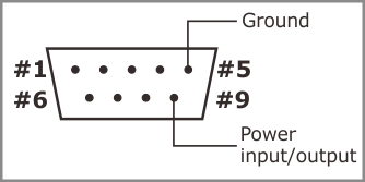
The DS1101 features a multichannel RS232 port. Physically, the port is implemented as a single DB9M connector with three output lines, four input lines, power input/output, and the ground.
Internally, the DS1101 has four independent serial ports. These are controlled through the ser. object.
Each of the four ports has its own TX and RX lines. These lines are implemented in hardware and can't be "remapped." The following table shows how the RX and TX lines are connected to the DB9M:
|
#1 |
RX4 (input, commonly DCD) |
|
#2 |
RX (input) |
|
#3 |
TX (output) |
|
#4 |
TX3 (output, commonly DTR) |
|
#5 |
Ground |
|
#6 |
RX3 (input, commonly DSR) |
|
#7 |
TX2 (output, commonly RTS) |
|
#8 |
RX2 (input, commonly CTS) |
|
#9 |
Power input/output ("12VDC") |
Each logical serial port of the ser. object also supports RTS/CTS flow control, which is implemented in firmware (TiOS). The ser.rtsmap and ser.ctsmap properties allow you to assign any general-purpose I/O (GPIO) line of the DS1101 to serve as the RTS or CTS line of any logical serial port. So, the TX2 and RX2 lines (pins 7 and 8) can be assigned to work as RTS and CTS lines, as is traditionally the case for RS232 ports. At the same time, these lines can be set to function as an independent serial channel.
The same goes for the DTR and DSR lines, except they don't even "exist" from the ser. object's perspective. These lines are implemented on the application level. For example, our Serial-over-IP application supports these lines. Again, instead of using TX3 and RX3 (pins 4 and 6) as the lines of an independent serial channel, it is possible to use them as DTR and DSR lines, as is common.
To simplify the discussion, let's look at the RS232 port from the Serial-over-IP application's point of view. This application defines 15 mapping options:
|
Mapping option |
Available signals |
Pins on the DB9M connector |
Missing line |
||||||
|
#2 |
#3 |
#8 |
#7 |
#6 |
#4 |
#1 |
|||
|
Option 0 |
RX/TX/CTS/RTS/DSR/DTR |
RX |
TX |
CTS |
RTS |
DSR |
DTR |
--- |
--- |
|
Option 1 |
RX/TX/CTS/RTS/DSR/DTR + RX/tx |
RX |
TX |
CTS |
RTS |
DSR |
DTR |
RX4 |
tx4 |
|
Option 2 |
RX/TX/CTS/RTS + RX/TX + RX/tx |
RX |
TX |
CTS |
RTS |
RX3 |
TX3 |
RX4 |
tx4 |
|
Option 3 |
RX/TX/CTS/RTS + RX/TX/CTS/rts |
RX |
TX |
CTS |
RTS |
RX3 |
TX3 |
CTS3 |
rts3 |
|
Option 4 |
RX/TX/CTS/RTS + RX/TX/DSR/dtr |
RX |
TX |
CTS |
RTS |
RX3 |
TX3 |
DSR3 |
dtr3 |
|
Option 5 |
RX/TX/DSR/DTR + RX/TX + RX/tx |
RX |
TX |
RX2 |
TX2 |
DSR |
DTR |
RX4 |
tx4 |
|
Option 6 |
RX/TX/DSR/DTR + RX/TX/CTS/rts |
RX |
TX |
RX2 |
TX2 |
DSR |
DTR |
CTS2 |
rts2 |
|
Option 7 |
RX/TX/DSR/DTR + RX/TX/DSR/dtr |
RX |
TX |
RX2 |
TX2 |
DSR |
DTR |
DSR2 |
dtr2 |
|
Option 8 |
RX/TX + RX/TX + RX/TX + RX/tx |
RX |
TX |
RX2 |
TX2 |
RX3 |
TX3 |
RX4 |
tx4 |
|
Option 9 |
RX/TX/CTS/rts + RX/TX + RX/TX |
RX |
TX |
RX2 |
TX2 |
RX3 |
TX3 |
CTS |
rts |
|
Option 10 |
RX/TX/DSR/dtr + RX/TX + RX/TX |
RX |
TX |
RX2 |
TX2 |
RX3 |
TX3 |
DSR |
dtr |
|
Option 11 |
RX/TX/CTS/RTS + RX/tx/CTS/RTS |
RX |
TX |
CTS |
RTS |
CTS4 |
RTS4 |
RX4 |
tx4 |
|
Option 12 |
RX/TX/CTS/RTS + RX/tx/DSR/DTR |
RX |
TX |
CTS |
RTS |
DSR4 |
DTR4 |
RX4 |
tx4 |
|
Option 13 |
RX/TX/DSR/DTR + RX/tx/CTS/RTS |
RX |
TX |
CTS4 |
RTS4 |
DSR |
DTR |
RX4 |
tx4 |
|
Option 14 |
RX/TX/DSR/DTR + RX/tx/DSR/DTR |
RX |
TX |
DSR4 |
DTR4 |
DSR |
DTR |
RX4 |
tx4 |
The "Available signals" column shows a particular combination of I/O lines for each option. For example, option 0 defines the standard serial port arrangement with RX, TX, CTS, RTS, DSR, and DTR lines. Option 2 gives you one channel with RX, TX, CTS, and RTS lines, one more channel with just RX and TX lines, and yet another channel with a single RX line. The TX line is "missing" because, once again, there are only three outputs available. This is why this line is shown in gray and lowercase (tx).