External Keypad Support
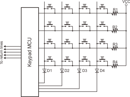
The WM2000 supports both matrix and binary keypads. A typical matrix keypad is shown in the schematic diagram below:
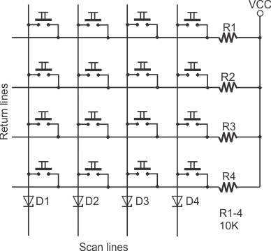
Due to flexible scan and return line mapping provided by the kp. object, you can assign any combination of GPIO lines to connect to your keypad. Up to eight scan and eight return lines can be assigned. Note that since the WM2000 only has ten GPIO lines, it isn't actually possible to connect an 8 x 8 keypad. The maximum matrix size is 5 x 4 (or 4 x 5).
On the WM2000, all scan lines must be configured as outputs and all return lines as inputs.
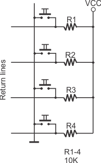
To build a keypad, you will need to have at least one return line. A sensible count of scan lines, however, starts from two! Having a single scan line is like having no scan lines — you might just as well ground this single scan line (i.e., always keep it active):
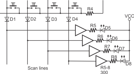
Scan lines can optionally perform the secondary function of driving LEDs. One such LED can be connected to each scan line, preferably through a buffer, as shown in the diagram below. These LEDs can be used for any purpose you desire — which can be completely unrelated to the keypad itself.
If the LEDs are connected as shown in the diagram, you turn them on by setting their corresponding control lines LOW.
Binary keypads (i.e., keypads that output binary key codes) do not require scanning — they contain a (typically microcontroller-based) circuit that performs the scanning and outputs encoded binary code of pressed keys. Such keypads are sometimes called "encoded keypads."
The WM2000 can work with binary keypads incorporating up to eight data lines.
For more information, see the documentation for the io. object and kp. object.