Wiegand and Clock/Data Circuit Examples
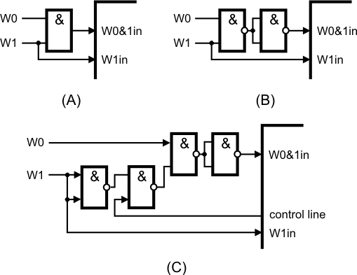
In Wiegand mode, a serial port's W0&1in input must receive a logical AND of W0 and W1 output from the attached Wiegand device. A simple AND gate will do the job (figure A). More popular than AND gates are NOR-AND gates, which can also be used (figure B).
If you are building a product that will also accept clock/data input, you may need to control whether the W0&1in input should receive a logical AND from both lines or just one of the lines. Figure C uses an additional I/O line of the device to control this. When the control line is HIGH, the W0&1in input receives a logical AND from both the W0 and W1 lines. When the control line is LOW, the W0&1in input receives just the signal from the W0 line. Four gates are required for this, so you can get away with using a single 74HC00 IC.