Connector Pin Assignment
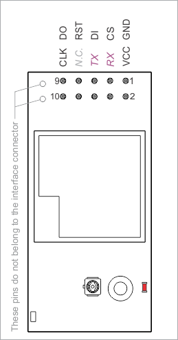
I/O Pin Assignment
|
Pin # |
Function |
Description |
|
1 |
GND |
System ground. |
|
2 |
VCC |
Positive power input, 3.3V nominal, ±5%. |
|
3 |
CS |
Chip select, active LOW (input*). |
|
4 |
RX |
UART, receive line (input*). |
|
5 |
DI |
SPI port, data in (input*, must be connected to DO line of the Tibbo host device). |
|
6 |
TX |
UART, transmit line (output*). |
|
7 |
RST |
Reset, active LOW (input*). |
|
8 |
N.C. |
No connection. |
|
9 |
DO |
SPI port, data out (output*, must be connected to DI line of Tibbo host device). |
|
10 |
CLK |
SPI port, clock (input*). |
* Of the WA2000
The UART of the WA2000 is currently unused but may be enabled in the future.