TB1004 Test Board
 This is a legacy device. The following information is provided as it was documented originally, albeit with some corrections and changes for clarity and style.
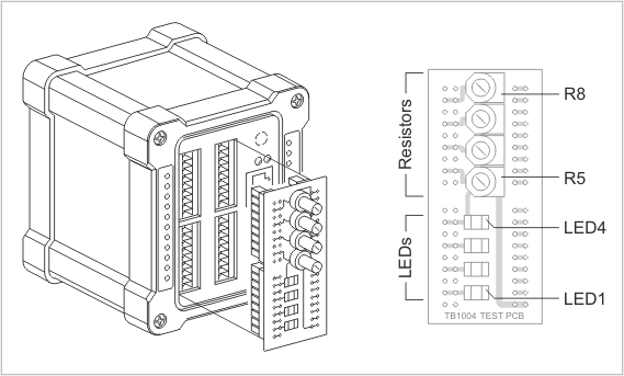
The TB1004 test board is provided for the convenience of evaluating the DS1004 controller (IB1004 + SB1004 boards). The board is basically a loopback, feeding the D/A outputs into the A/D inputs of the DS1004. The schematic diagram of the test board's connections is shown below:
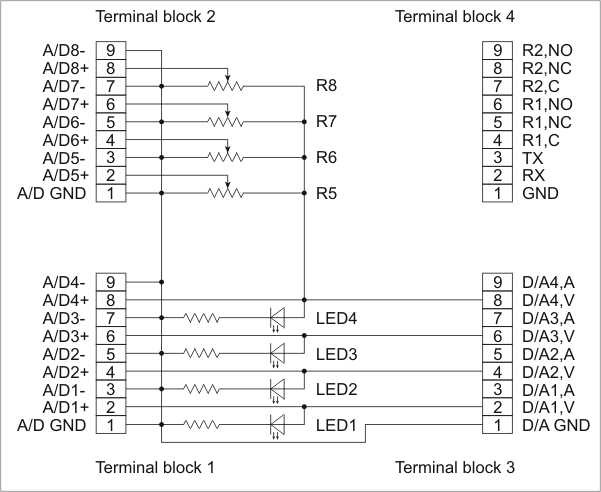
The voltage outputs of D/A channels 1~4 are connected directly to A/D inputs 1~4 and also to red LEDs 1~4. The brightness of these LEDs is proportional to the voltage on D/A outputs. Obviously, the LEDs will only work for positive output voltages and will stay off for negative voltages. Thus, the LEDs provide indication only for half of the D/As' output range.
The current outputs of the D/A channels are not used at all and can't be tested with the TB1004.
A/D inputs 4~8 are wired into the circuit through adjustable resistors R1~4. The voltage for these resistors comes from D/A output 4. Therefore, the voltages on the central taps of R1~4 are a fraction of the current output of D/A 4.