TB100 Terminal Block Adapter
 This is a legacy device. The following information is provided as it was documented originally, albeit with some corrections and changes for clarity and style.
The TB100 Terminal Block Adapter attaches to a DB9M connector. The TB100 provides a convenient way of wiring RS422 and RS485 lines to the serial port of a Tibbo device. The wires are inserted into the terminal contacts and the terminals are then tightened using a screwdriver.
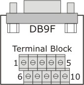
The following table details the terminal block contact functions in the RS232, RS422, and RS485 modes of operation. The table assumes that the TB100 is connected to a Tibbo device with a universal serial port that has a DB9M connector.
|
Pin |
RS232 |
RS422 |
RS485 |
|
#2 |
<No connection> |
RTS– (output) |
<No connection> |
|
#7 |
RX (input) |
RX– (input) |
RX– (input) |
|
#8 |
TX (output) |
TX+ (output) |
TX+ (output) |
|
#9 |
DTR (output) |
TX– (output) |
TX– (output) |
|
#10 |
Ground |
Ground |
Ground |
|
#6 |
DSR (input) |
RX+ (input) |
RX+ (input) |
|
#1 |
RTS (output) |
RTS+ (output) |
<No connection> |
|
#3 |
CTS (input) |
CTS+ (input) |
<No connection> |
|
#4 |
<No connection> |
CTS– (input) |
<No connection> |
Although Tibbo devices support half-duplex RS485 communications, the TX and RX lines remain independent on these devices even in the RS485 mode. In order to arrange a two-wire half-duplex RS485 bus, you need to externally connect RX+ to TX+ and RX– to TX–. On the TB100, this is conveniently done by closing (putting to ON position) two switches: SW1 and SW2. These are located on the back of the TB100.
Additionally, the TB100 provides termination circuits typically needed at the end of long RS422 or RS485 lines. There are four identical terminators that can be switched on and off individually using four switches located on the back of the TB100. The following table details to which line pairs the terminators can be connected:
|
SW3 |
CTS+/CTS– |
|
SW4 |
RTS+/RTS– |
|
SW5 |
RX+/RX– |
|
SW6 |
TX+/TX– |
The schematic diagram for one of the terminators is shown in the figure below:

If you are using the RS485 mode (SW1 and SW2 are closed) and you want to terminate the RS485 bus, then you only need to close either SW5 or SW6. Having both switches closed will effectively add two termination circuits to the same bus!