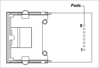
Interface Pads
The RJ203 has a single row of interface pins.
|
Pin |
Function |
Type |
Description |
|
#1 |
RX+ |
Output |
Ethernet port, positive line of the differential input signal pair |
|
#2 |
RX– |
Output |
Ethernet port, negative line of the differential input signal pair |
|
#3 |
AVCC |
Input |
"Clean" 1.8V power output for magnetics circuitry |
|
#4 |
--- |
--- |
--- |
|
#5 |
--- |
--- |
--- |
|
#6 |
GND |
Ground |
|
|
#7 |
TX+ |
Input |
Ethernet port, positive line of the differential output signal pair |
|
#8 |
TX– |
Input |
Ethernet port, negative line of the differential output signal pair |