UART Mode
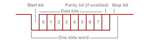
In the UART mode, the serial port has standard UART functionality. You can select the baudrate, parity, number of bits in each character, and full or half-duplex operation (see Serial Settings). The UART works with signals of "TTL-serial" polarity — the RX and TX lines are at logical HIGH when no data transmission is taking place, the start bit is LOW, and the stop bit is HIGH (shown below for the case of 8 bits/character and enabled parity).
UART data is sent and received via the TX output and RX input lines. Two additional lines — RTS output and CTS input — may also be used depending on the serial port setup (see below).
 Please remember that depending on the platform, you may be required to configure some or all of your serial port's lines as inputs or outputs through the io.enabled property of the io. object. Additionally, you may have the freedom of remapping certain serial port lines to different I/O pins of the device if required. For more information, refer to your device's platform documentation (for example, the EM1000's is here).
How the Serial Port Sends and Receives UART Data
The serial port can send and receive the data with no parity, or with the even, odd, mark, or space parity configuration. Additionally, you can specify the number of bits in each character (7 or 8). The serial port takes care of parity calculation automatically. When the parity bit is enabled, the serial port will automatically calculate the parity bit value for each character it transmits. When receiving, the serial port will correctly process incoming characters based on the specified number of bits and parity mode.
An actual parity check is not performed: The serial port will receive the parity bit, but won't actually check if it is correct. The parity option has been mostly kept for compatibility with older devices, so the serial port transmits it correctly.
How the UART Data Is Stored in the RX and TX Buffers of the Serial Port
When in the UART mode, each data byte in the TX or RX buffer of the serial port represents one character. When the serial port is configured to send and receive 7-bit characters, the most significant bit of each byte in the RX buffer will be 0 and the most significant bit of each byte in the TX buffer will be ignored. Parity bits are not stored in the buffers. For the outgoing data stream, the serial port will calculate and append the parity bit automatically. For the incoming serial data, the serial port will discard the parity bit so the RX buffer will only get "pure" data.
Full-Duplex Operation
The full-duplex mode of operation is suitable for communicating with RS232, RS422 devices, four-line RS485 devices, and most TTL-serial devices. Naturally, an external transceiver IC is needed for RS232, RS422, or RS485. TTL-serial devices can be connected to the serial port lines directly in most cases.
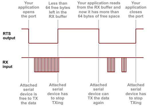
In the full-duplex mode, the RTS output and CTS input lines can be used for optional flow control. The RTS output is LOW whenever the serial port is ready to receive the data from "attached" serial device (the port is opened and the RX buffer has at least 64 bytes of free space). The RTS line is HIGH whenever the serial port is closed or the RX buffer has less than 64 bytes of free space left. The figure below illustrates RTS operation.
 All diagrams show TTL-serial signals. If you are dealing with the lines of the RS232 port, you will see all signals in reverse!
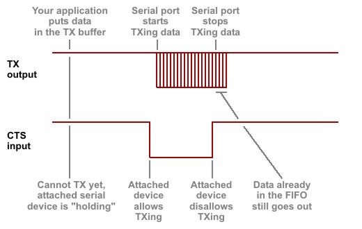
The CTS input is used by the serial port to check if the attached serial device is able to accept the data. The serial port will only start to send the data when the CTS input is LOW. The serial port will stop sending the data once the line goes HIGH. Note, that some Tibbo devices have a hardware buffer called "FIFO" ("first-in-first-out"). Once the TX data is in the FIFO, it will be sent out even if the CTS line goes LOW. Therefore, after the attached serial device switches the CTS line to LOW, the serial port may still output the number of bytes not exceeding the capacity of the FIFO. For more information, refer to your device's platform documentation (for example, EM1000's is here).
When flow control is enabled, the RTS and CTS lines are controlled by the serial port and cannot be manipulated by your application. When flow control is off, your application can set and read the state of these lines through the io. object.
Half-Duplex Operation
The half-duplex mode of operation is suitable for communicating with two-wire RS485 devices. Again, an appropriate interface transceiver IC is required to be connected to the serial port.
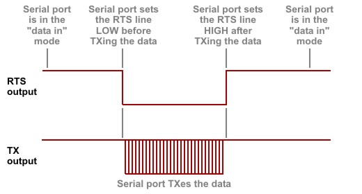
In the half-duplex mode, the RTS output is used to control data transmission direction. You can select the polarity of the direction control signal (i.e., which state will serve as the "data in" direction and which as the "data out" direction — see Serial Settings).
When the serial port has no data to transmit (the TX buffer is empty), it is always ready to receive data, so the RTS line is in the "data in" state. When the serial port needs to send out some data (the TX buffer is not empty), it switches the RTS line into the "data out" state, transmits the data, then switches the RTS line back into the "data in" state. Assuming "LOWFORINPUT" direction control polarity, direction control looks like this:
The CTS line is not controlled by the serial port when in the half-duplex mode. Your application can manipulate this line through the io. object.