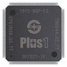
Plus1 (SP7021) CPU

Introduction
Although there are many embedded Linux CPUs on the market, few were designed to directly address the needs of the IoT and industrial control markets. Most CPUs found on popular boards such as the Raspberry Pi were initially meant for something else (for example, a set-top box) and were merely repurposed for the needs of the IoT and industrial control communities.
Such CPUs usually have adequate processing power but lack I/O features, which is not surprising: Set-top boxes have very different I/O needs than IoT or industrial control devices. These CPUs are also rather complex, need multiple additional components to work, are available only in difficult-to-handle BGA packaging, and require six or eight-layer boards. All this poses severe obstacles to low and medium-volume device vendors.
Take the BGA packaging as an example. Everything about BGA is an order of magnitude more complex compared to other packaging choices, such as LQFP. BGA represents the cut-off line, where it becomes impossible to handle the chips manually. Everything from soldering to desoldering and verifying the assembly quality requires specialized and expensive equipment. Smartphone manufacturers accept BGA challenges as the inevitable side effect of the desired board miniaturization that the technology enables, but vendors of IoT or industrial control devices view this differently. IoT and industrial control products rarely have any size pressure, and having to deal with ever-smaller IC packages only brings complications without any apparent benefits.
As another example, consider the logic levels of GPIO lines. As processor designs take advantage of ever-more advanced fabrication processes, chip supply voltages have also decreased. Subsequently, standard semiconductor I/O libraries have dropped support for 5V and even 3.3V logic levels. This did not bother the designers of set-top boxes and other "closed" products but was bad news for the architects of control hardware.
To summarize, there was an apparent gap between existing processor offerings and the requirements of IoT and industrial control applications. Recognizing the unmet needs of IoT and industrial control vendors, Sunplus Technology Co., Ltd. and Tibbo Technology, Inc. in late 2017 set out to develop a Linux-grade chip that would directly address these markets. The idea was to create a powerful SoC with I/O features and packaging specifically targeting IoT and industrial control applications, as well as the needs of low-to-medium-volume hardware manufacturers. Thus, the Plus1 concept was born.
Key Features
- Easy-to-use LQFP package
- Quad-core 1GHz Cortex-A7 CPU, plus A926 and 8051 cores
- Single 3.3V power
- Integrated 128MB or 512MB DDR3 DRAM
- Eight 8-bit 5V-tolerant I/O ports, plus one high-current port
- Flexible Peripheral Multiplexing (PinMux)
- Dual PinMuxable Ethernet MACs
- In the switch configuration, the OS is presented a single Ethernet adapter
- In the dual-port configuration, the OS detects two independent Ethernet adapters
- Four PinMuxable Enhanced UARTs, plus one console UART
- Industrial operating temperature range: –40°C to 85°C
- Low EMI simplifies certification
- Modern, Yocto-based Linux distribution
- Flash interface supporting eMMC, SPI NAND, and SPI NOR memories
- PinMuxable SD2.0 interface
- PinMuxable SDIO (SD2.0) interface (intended for connecting a Wi-Fi/BT module)
- Two OTG USB2.0 ports with Linux boot and USB video class support
- Four PinMuxable buffered SPI modules
- Four PinMuxable buffered I²C modules
- Two PinMuxable four-channel PWM modules
- Four PinMuxable timers/counters
- Four PinMuxable capture modules
- MIPI-CSI camera interface for up to two cameras supporting resolutions up to 1328x864 @ 60 fps
- MIPI video interface supporting resolutions up to 1366x768 and 1312x816
- HDMI 1.4 video interface for connecting monitors with up to 720p resolution
- TFT LCD controller with parallel bus interface (resolution up to 320x240x24)
- I²S/SPDIF/PWM audio output for up to five channels
- PDM interface for an eight-channel MEMS microphone array
- 32-bit FPGA bus I/O (FBIO) interface
- Temperature sensor for estimating the internal temperature of the IC
- Real-time clock (RTC) with an alarm (system power on) function, dedicated backup power input, and backup battery (supercapacitor) charging circuit
- 128-byte one-time programmable (OTP) memory carrying vendor/device IDs, two registered MAC addresses, as well as providing 64-byte space for user data
- SWD and JTAG debug interfaces
- Watchdog timer
- Secure boot: boot image verified by ED25519 algorithm
- PKA engine (RSA), hash engine (SHA3, MD5), and encryption/decryption engine (AES)
