D/A Converter
The D/A converter is based on the Analog Devices' 14-bit AD7836 chip and has four independent output channels with 14-bit resolution. Each of the four channels has independent voltage and current output lines (both can be used at the same time if needed).
Each channel has two outputs: one voltage and one current output. The voltage outputs have ±10V range (20mA max load). Writing all 1's (14 of them) into the D/A channel produces the maximum positive level on the voltage output (+10V nominal), while writing all 0's produces the maximum negative level on the voltage output (–10V nominal). Writing a "middle" binary value of "10000000000000" (that's 1 followed by 13 zeroes) produces a 0V output. Of course, this explanation is idealized, as it doesn't take into account inevitable conversion errors.
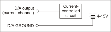
The output current range on the current output is 0~20mA. An external 4V~15V power source is required for current outputs to work. Writing all 1's into the D/A channel results in the maximum output current. Writing a middle value ("10000000000000") results in zero current. Writing any value below that still produces zero current. Hence, the actual resolution of the current output is not 14, but 13 bits.
The D/A converter has full galvanic isolation from the rest of the IB1004 + SB1004 circuitry: The power for the D/A section is generated by an isolated switching power supply; all control lines use opto-couplers.
D/A Outputs
All D/A-related lines are available on nine-pin terminal block #3:
|
Terminal # |
Function |
|
9 |
D/A channel 4, current output |
|
8 |
D/A channel 4, voltage output |
|
7 |
D/A channel 3, current output |
|
6 |
D/A channel 3, voltage output |
|
5 |
D/A channel 2, current output |
|
4 |
D/A channel 2, voltage output |
|
3 |
D/A channel 1, current output |
|
2 |
D/A channel 1, voltage output |
|
1 |
D/A ground (isolated from the rest of the device) |
D/A Control
Four lines of the EM1000 (located on the NB10x0 network board) control the D/A converter. In the table below, "output" means an output of the EM1000 and "input" means an input of the EM1000:
|
Line |
Function |
Corresponding EM1000 I/O line |
IC1000 cable line |
|
DATA (output) |
Serial data |
GPIO11 |
23 |
|
CLOCK (output) |
Serial clock (LOW idle state) |
GPIO1 |
3 |
|
WR (output) |
Data latch strobe (active LOW) |
GPIO34 |
26 |
|
EN (output) |
Output enable:
|
GPIO35 |
24 |
*GPIO line configured as input (default state)
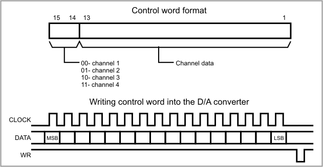
The D/A converter control cycle consists of the following steps. First, a 16-bit data word is serially clocked into the D/A circuit. Bits 15 and 14 of the data word select the output channel, and the remaining 14 bits carry the desired output value. The word is sent most significant bit first.
Two lines — CLOCK and DATA — are used for sending the data word to the D/A converter. The inactive state for the CLOCK line is LOW. Each write transaction consists of 16 clock pulses. With each LOW-to-HIGH transition on the CLOCK line, the state of the DATA line is latched into the D/A converter. The process is illustrated below.
Once all 16 bits have been clocked in, the negative pulse on the WR line sets new data and the new analog value appears on the outputs of the corresponding D/A channel (provided that the EN line is LOW).
The EN line is used for enabling the analog outputs of the D/A converter. The system powers up with EN line pulled HIGH internally. This disables the D/A converter and produces 0V (0mA) on its outputs. Taking the EN line LOW will enable the D/A. Before that, your application should write the desired value into each D/A channel. Failure to do so will result in the unknown voltage (current) output levels once the EN line is set LOW.
Remember that you need to configure all four control lines of the EM1000 as outputs.
Clock Speed Limitations
The D/A converter is electrically isolated from the rest of the device, so there are opto-couplers on all interface lines. Opto-couplers are relatively slow devices, which imposes a limit on how fast the CLOCK line can be toggled. The minimum clock period is 200µs. Both half-periods must be at least 100µs long. The minimum pulse width on the WR line is also 100µs. This means that the new value can be output to the converter in 200µS * 16 + 100 = 3.3ms.