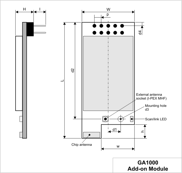
Mechanical Dimensions
|
L |
Max. |
42.1 |
Module length. |
|
W |
Max. |
19.1 |
Module width. |
|
H |
Max. |
6.7 |
Module height. |
|
I |
Min. |
4.0 |
Pin length. |
|
w |
Min |
11.7 |
Horizontal cutout dimension. |
|
h |
Min. |
4.5 |
Vertical cutout dimension. |
|
d1 |
Avg. |
4.5 |
Horizontal distance from the centerline of the module to the center of the mounting hole. |
|
d2 |
Avg. |
35.0 |
Vertical distance from the edge of the board to the center of the mounting hole. |
|
d3 |
Min. |
2.1 |
Mounting hole diameter |
|
d4 |
Avg. |
1.4 |
Vertical distance from the edge of the board to the center of the first row of pins of the connector |
|
p |
Avg. |
2.54 |
Pin pitch |
Dimensions are for reference only. Tibbo assumes no responsibility for any errors in this manual, and does not make any commitment to update the information contained herein.