Ethernet Port Lines
The EM510 has a 10/100BaseT Ethernet port. The onboard electronics of the EM510 do not include Ethernet magnetics, so the magnetics circuitry must be connected externally to the TX+, TX–, RX+, RX–, and AVCC pins. The AVCC pin outputs clean power for the magnetics circuitry, which is very sensitive to noise.
Please, note the following:
- The AVCC is an output!
- Do not combine the AVCC with the VCC (main power) pin.
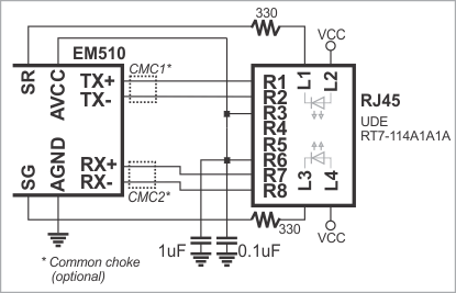
You can use either a standalone magnetics part, or an RJ45 jack with integrated magnetics (recommended). Here is a circuit diagram based on the UDE RT7-114A1A1A part:
It is important to make the PCB wire connections between the pins of the EM510 and RJ45 jack (magnetics circuitry) as short as possible. Making the wires too long may cause the noise level generated by your PCB to surpass the maximum radiated emission limits set by FCC/CE regulations. Additionally, longer Ethernet lines on the PCB will make Ethernet operation less stable.
Note that the circuit above shows an RJ45 jack with two LEDs. Further information on the use of these LEDs can be found in LED Lines.