Ethernet Lines and Jack/Magnetics Data
 This is a legacy product. The following is provided as it was documented originally, albeit with some corrections and changes for clarity and style.
Pin Functions and Descriptions
|
Pin Number |
Signal Name |
Direction |
Description |
|
Mag. conn., #1 |
RX+ |
Input |
Ethernet port, positive line of the differential input signal pair |
|
Mag. conn., #2 |
RX- |
Input |
Ethernet port, negative line of the differential input signal pair |
|
Mag. conn., #9 |
TX+ |
Output |
Ethernet port, positive line of the differential output signal pair |
|
Mag. conn., #10 |
TX- |
Output |
Ethernet port, negative line of the differential output signal pair |
|
Mag. conn., #11 |
AVCC |
Output |
"Clean" 3.3V power output for magnetics circuitry |

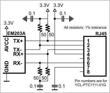
Ethernet port of the EM203A is of 100/10BaseT type. Onboard electronics of the EM203A do not include Ethernet magnetics, so magnetics circuitry must be connected externally to pins TX+, TX-, RX+, RX-, and AVCC. The AVCC pin outputs clean power for the magnetics circuitry, which is very sensitive to noise. The voltage on the AVCC output is 3.3V.
 Do not interconnect the AVCC and VCC pins! This will permanently damage the EM203A.
One of the options for implementing the Ethernet front-end is to use RJ203 jack/magnetics module.
