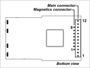
I/O Pin Assignment and Pin Functions
EM203 has two connectors:
- Main Connector
- Magnetics Connector
Depending on the EM203 version, the magnetics connector can be soldered facing up or down, as described in Mechanical Dimensions.

Pin Functions and Descriptions
Main Connector
|
Pin Number |
Signal Name |
Direction |
Description |
|
#1 |
MD* |
Input |
Mode selection pin |
|
#2 |
RST |
Input |
Reset, active high |
|
#3 |
P3 DTR* |
Input/output Output |
General-purpose input/output line Data terminal ready output |
|
#4 |
P2 DSR* |
Input/output Input |
General-purpose input/output line Data set ready input |
|
#5 |
L3 SG* |
Output Output |
LED output 3 Green status LED control line |
|
#6 |
L4 SR* |
Output Output |
LED output 4 Red status LED control line |
|
#7 |
VCC |
|
Positive power input, 5V nominal, +/- 5%, app. 220mA |
|
#8 |
GND |
|
Ground |
|
#9 |
RX |
Input |
Serial receive line |
|
#10 |
TX |
Output |
Serial transmit line |
|
#11 |
P4 CTS/SEL* |
Input/output Input |
General-purpose input/output line Clear to send input; full-/half-duplex selection input |
|
#12 |
P5 RTS/DIR* |
Input/output Output |
General-purpose input/output line Request to send output (full-duplex mode); data direction control output (half-duplex mode) |
* Implemented in (supported through) firmware.
Line functions defined by the Application Firmware are shown in blue.
Magnetics Connector
|
Pin Number |
Signal Name |
|
#1 |
RX+ |
|
#2 |
RX- |
|
#3 |
AVCC |
|
#4 |
--- |
|
#5 |
--- |
|
#6 |
GND |
|
#7 |
TX+ |
|
#8 |
TX- |
